C 0617-13:2011
(1)
2019年7月1日の法改正により名称が変わりました。まえがきを除き,本規格中の「日本工業規格」を「日本産業規格」に読み替えてください。
目 次
ページ
序文 ··································································································································· 1
1 適用範囲 ························································································································· 1
2 引用規格 ························································································································· 1
3 概要······························································································································· 2
4 電気用図記号及びその説明 ································································································· 4
第II章 入力,出力及び他の接続に関連する限定する図記号 ························································ 6
第4節 信号の種類を示す限定図記号 ······················································································ 6
第5節 入力,出力及び他の接続に関連する限定図記号 ····························································· 11
第III章 算術演算機能を果たす素子 ······················································································ 38
第6節 総則 ······················································································································ 38
第7節 算術演算機能を果たす素子の例 ·················································································· 39
第8節 増幅器 ··················································································································· 41
第9節 増幅器の例 ············································································································· 43
第IV章 変換器 ················································································································· 53
第10節 一般 ····················································································································· 53
第11節 変換器の例 ············································································································ 55
第V章 調整器,比較器······································································································· 60
第12節 電圧調整器 ············································································································ 60
第13節 電圧調整器の例 ······································································································ 61
第14節 比較器 ·················································································································· 64
第15節 比較器の例 ············································································································ 65
第VI章 その他 ················································································································· 67
第16節 複合機能素子の例 ··································································································· 67
第17節 電子スイッチの例 ··································································································· 68
第18節 その他のデバイス ··································································································· 70
5 注釈······························································································································ 71
附属書A(参考)参考文献 ···································································································· 90
C 0617-13:2011
(2)
2019年7月1日の法改正により名称が変わりました。まえがきを除き,本規格中の「日本工業規格」を「日本産業規格」に読み替えてください。
まえがき
この規格は,工業標準化法に基づき,日本工業標準調査会の審議を経て,経済産業大臣が改正した日本
工業規格である。
これによって,JIS C 0617-13:1999は改正され,この規格に置き換えられた。
この規格は,著作権法で保護対象となっている著作物である。
この規格の一部が,特許権,出願公開後の特許出願又は実用新案権に抵触する可能性があることに注意
を喚起する。経済産業大臣及び日本工業標準調査会は,このような特許権,出願公開後の特許出願及び実
用新案権に関わる確認について,責任はもたない。
JIS C 0617の規格群には,次に示す部編成がある。
JIS C 0617-1 第1部:概説
JIS C 0617-2 第2部:図記号要素,限定図記号及びその他の一般用途図記号
JIS C 0617-3 第3部:導体及び接続部品
JIS C 0617-4 第4部:基礎受動部品
JIS C 0617-5 第5部:半導体及び電子管
JIS C 0617-6 第6部:電気エネルギーの発生及び変換
JIS C 0617-7 第7部:開閉装置,制御装置及び保護装置
JIS C 0617-8 第8部:計器,ランプ及び信号装置
JIS C 0617-9 第9部:電気通信−交換機器及び周辺機器
JIS C 0617-10 第10部:電気通信−伝送
JIS C 0617-11 第11部:建築設備及び地図上の設備を示す設置平面図及び線図
JIS C 0617-12 第12部:二値論理素子
JIS C 0617-13 第13部:アナログ素子
2019年7月1日の法改正により名称が変わりました。まえがきを除き,本規格中の「日本工業規格」を「日本産業規格」に読み替えてください。
日本工業規格 JIS
C 0617-13:2011
電気用図記号−第13部:アナログ素子
Graphical symbols for diagrams−Part 13: Analogue elements
序文
この規格は,2001年にデータベース形式規格として発行されメンテナンスされているIEC 60617の2008
年時点での技術的内容を変更することなく作成した日本工業規格である。
なお,IEC 60617は,部編成であった規格の構成を一つのデータベース形式規格としたが,JISでは,規
格の利便性も考慮し,これまでどおり部ごとの分冊構成とし,構成方法を変更している。
1
適用範囲
この規格は,電気用図記号のうち,アナログ素子に関する図記号について規定する。
注記1 この規格はIEC 60617のうち,従来の図記号番号が13-04-01から13-18-01までのもので構成
されている。
注記2 この規格の対応国際規格及びその対応の程度を表す記号を,次に示す。
IEC 60617,Graphical symbols for diagrams(MOD)
なお,対応の程度を表す記号“MOD”は,ISO/IEC Guide 21-1に基づき,“修正している”
ことを示す。
2
引用規格
次に掲げる規格は,この規格に引用されることによって,この規格の規定の一部を構成する。これらの
引用規格のうちで,西暦年を付記してあるものは,記載の年の版を適用し,その後の改正版(追補を含む。)
は適用しない。西暦年の付記がない引用規格は,その最新版(追補を含む。)を適用する。
JIS C 0452-2 電気及び関連分野−工業用システム,設備及び装置,並びに工業製品−構造化原理及び
参照指定−第2部:オブジェクトの分類(クラス)及び分類コード
注記 対応国際規格:IEC 61346-2,Industrial systems, installations and equipment and industrial products
−Structuring principles and reference designations−Part 2: Classification of objects and codes for
classes(IDT)
JIS C 0456 電気及び関連分野−電気技術文書に用いる符号化図形文字集合
注記 対応国際規格:IEC 61286,Information technology−Coded graphic character set for use in the
preparation of documents used in electrotechnology and for information interchange(IDT)
JIS C 0617-1 電気用図記号−第1部:概説
注記 対応国際規格:IEC 60617,Graphical symbols for diagrams(MOD)
JIS C 0617-2 電気用図記号−第2部:図記号要素,限定図記号及びその他の一般用途図記号
注記 対応国際規格:IEC 60617,Graphical symbols for diagrams(MOD)
2
C 0617-13:2011
2019年7月1日の法改正により名称が変わりました。まえがきを除き,本規格中の「日本工業規格」を「日本産業規格」に読み替えてください。
JIS C 0617-12 電気用図記号−第12部:二値論理素子
注記 対応国際規格:IEC 60617,Graphical symbols for diagrams(MOD)
JIS C 1082-1 電気技術文書−第1部:一般要求事項
注記 対応国際規格:IEC 61082-1:1991,Preparation of documents used in electrotechnology−Part 1:
General requirements(MOD)
JIS X 0221 国際符号化文字集合(UCS)
注記 対応国際規格:ISO/IEC 10646,Information technology−Universal Multiple-Octet Coded
Character Set (UCS)(IDT)
JIS Z 8222-1 製品技術文書に用いる図記号のデザイン−第1部:基本規則
注記 対応国際規格:ISO 81714-1,Design of graphical symbols for use in the technical documentation of
products−Part 1: Basic rules(IDT)
IEC 60027 (all parts),Letter symbols to be used in electrical technology (partly being replaced by ISO/IEC
80000)
3
概要
JIS C 0617の規格群は,次の部によって構成されている。
第1部:概説
第2部:図記号要素,限定図記号及びその他の一般用途図記号
第3部:導体及び接続部品
第4部:基礎受動部品
第5部:半導体及び電子管
第6部:電気エネルギーの発生及び変換
第7部:開閉装置,制御装置及び保護装置
第8部:計器,ランプ及び信号装置
第9部:電気通信−交換機器及び周辺機器
第10部:電気通信−伝送
第11部:建築設備及び地図上の設備を示す設置平面図及び線図
第12部:二値論理素子
第13部:アナログ素子
図記号は,JIS Z 8222-1に規定する要件に従って作成している。基本単位寸法としてM=5 mmを用いた。
多数の端子を表示する必要,又はその他の配置要件に応じてスペースをとる必要がある場合は,JIS Z
8222-1の7.[比率(proportion)の変更]に従い,図記号の寸法(高さなど)を変更してもよい。
拡大,縮小したり寸法を変更した場合も,線の太さは,拡縮せず,元のままとする。
図記号は,関連線間の間隔が基本単位の倍数になるよう描かれている。端子表示が必要な場合のスペー
スがとれるように基本単位2Mを選択した。図記号は同じグリッドを用い,分かりやすい大きさに描かれ
ている。図記号は,全てコンピュータ支援製図システムのグリッド内に描かれている(図記号の背景にグ
リッドを表示した。)。
第12部及び第13部についてはIEC 60617の該当図記号にグリッドがないため,国際規格に従って,グ
リッドなしの表記とした。
3
C 0617-13:2011
2019年7月1日の法改正により名称が変わりました。まえがきを除き,本規格中の「日本工業規格」を「日本産業規格」に読み替えてください。
JIS C 0617規格群で規定する全ての図記号の索引を,JIS C 0617-1に示す。
この規格に用いる項目名の説明を表1に示す。
なお,英文の項目名は,IEC 60617に対応した名称である。
表1−図記号の規定に用いる項目名の説明
項目名
説明
図記号番号
図記号の分類番号。xx-yy-zzの形式で示し,x,y,z は0〜9の整数とAとで表す。
xx:部番号
yy:節番号
zz:節番号中の図記号番号
注記 節番号にAが付いた図記号は,旧規格に規定されていたが,現在は削除されて
いる。
識別番号
(Symbol identity number)
図記号の識別番号。Snnnnnの形式で示し,nは0〜9の整数である。この番号はIEC 60617
の固有番号である識別番号(Symbol identity number)に対応しており,番号付けには意味
はない。
名称
(Name)
当該図記号の概念を表す名称。
別の名称
(Alternative names)
当該図記号の名称に対する別な名称。ほぼ同意語で,従属的な特定の名称など。
様式
(Form)
当該図記号と同一の名称(意味)。形状の異なる図記号がある場合,様式1,様式2…と
して記載する。
別様式
(Alternative forms)
当該図記号と同一名称でほかの様式の図記号がある場合,その図記号の図記号番号。
注釈
(Application notes)
当該図記号の説明又は付加的な関連規定。注釈は通常,複数の図記号で共有されるため,
注釈番号を記した別のページに記載されている。
注釈番号はAnnnnnの形式で示し,nは0〜9の整数で表す。この番号はIEC 60617の注
釈(Application notes)に対応しており,番号付けには意味はない。
適用分類
(Application class)
当該図記号が適用される文書の種類。JIS C 1082-1で定義されている。
機能分類
(Function class)
当該図記号が属する一つ又は複数の分類。JIS C 0452-2で定義されている。括弧内に示し
たものは,分類コード。
形状分類
(Shape class)
当該図記号を特徴付ける基本的な形状。
制限事項
(Symbol restrictions)
当該図記号の適用方法に関する制限事項。
補足事項
(Remarks)
当該図記号の付加的な情報。
適用図記号
(Applies)
当該図記号を構築するために用いている図記号(図記号要素,限定図記号及び一般図記
号)の識別番号。
被適用図記号
(Applied in)
当該図記号を要素として用いている図記号の識別番号。
キーワード
(Keywords)
検索を容易にするキーワードの一覧。
4
C 0617-13:2011
2019年7月1日の法改正により名称が変わりました。まえがきを除き,本規格中の「日本工業規格」を「日本産業規格」に読み替えてください。
表1−図記号の規定に用いる項目名の説明(続き)
項目名
説明
注記
この規格に関する注記を示す。
なお,IEC 60617だけの参考情報としては,次の項目がある。
Status level
IEC 60617連続メンテナンスに関する当該図記号の状態。
当該図記号が承認された場合,そのステータスレベルは“Standard”に設
定される。
当該図記号が後に別の図記号で置き換えられた場合,又は技術的に旧式
であると判断された場合,そのステータスレベルは参考としての“旧形
式(Obsolete)”となる。
技術的に旧式になった場合,当該図記号は用いられるが,今後メンテナ
ンスは行われない。
Released on
IEC 60617の一部として発行された年月日。
Obsolete from
IEC 60617に対して旧形式となった年月日。
4
電気用図記号及びその説明
第I章 一般
第1節 適用範囲(箇条1を参照。)
第2節 引用規格(箇条2を参照。)
第3節 一般的注記[箇条5(注釈A00352の箇条2)を参照。]
この規格の第II章から第VI章は,次のとおりとする。英語表記は,IEC 60617によるもので,参考とし
て示す。
第II章 入力,出力及び他の接続に関連する限定する図記号
第4節 信号の種類を示す限定図記号
第5節 入力,出力及び他の接続に関連する限定図記号
第III章 算術演算機能を果たす素子
第6節 総則
第7節 算術演算機能を果たす素子の例
第8節 増幅器
第9節 増幅器の例
第IV章 変換器
第10節 一般
第11節 変換器の例
第V章 調整器,比較器
第12節 電圧調整器
第13節 電圧調整器の例
第14節 比較器
第15節 比較器の例
第VI章 その他
第16節 複合機能素子の例
第17節 電子スイッチの例
5
C 0617-13:2011
2019年7月1日の法改正により名称が変わりました。まえがきを除き,本規格中の「日本工業規格」を「日本産業規格」に読み替えてください。
第18節 その他のデバイス
6
C 0617-13:2011
2019年7月1日の法改正により名称が変わりました。まえがきを除き,本規格中の「日本工業規格」を「日本産業規格」に読み替えてください。
第II章 入力,出力及び他の接続に関連する限定する図記号
第4節 信号の種類を示す限定図記号
図記号番号
(識別番号)
図記号(Symbol)
13-04-01
(S01748)
項目
説明
IEC 60617情報(参考)
名称
アナログ入力
Analogue input
別の名称
−
−
様式
−
−
別様式
−
−
注釈
A00321,A00352
適用分類
限定図記号
Qualifiers only
機能分類
機能属性だけ(-)
- Functional attribute only
形状分類
文字
Characters
制限事項
−
−
補足事項
図記号は,JIS C 0456アナログ記号の文字4/9
として定義されている。JIS X 0221
“INTERSECTION”のUCS 2229(表77)と
同等である。
The symbol is defined as character 4/9 of IEC 61286
"ANALOGUE SYMBOL", equivalent to UCS 2229
(Table 61) of ISO/IEC 10646 "INTERSECTION".
適用図記号
S00216
被適用図記号
S01604,S01602,S01793,S01792
キーワード
アナログ,アナログ素子,演算素子,二進論
理素子,接続
analogue, analogue elements, arithmetic elements,
binary logic elements, connections
注記
−
Status level
Standard
Released on
2004-09-13
Obsolete from
−
7
C 0617-13:2011
2019年7月1日の法改正により名称が変わりました。まえがきを除き,本規格中の「日本工業規格」を「日本産業規格」に読み替えてください。
第4節 信号の種類を示す限定図記号
図記号番号
(識別番号)
図記号(Symbol)
13-04-02
(S01749)
項目
説明
IEC 60617情報(参考)
名称
アナログ出力
Analogue output
別の名称
−
−
様式
−
−
別様式
−
−
注釈
A00321,A00352
適用分類
限定図記号
Qualifiers only
機能分類
機能属性だけ(-)
- Functional attributes only
形状分類
文字
Characters
制限事項
−
−
補足事項
図記号は,JIS C 0456アナログ記号の文字4/9
として定義されている。JIS X 0221
“INTERSECTION”のUCS 2229(表77)と
同等である。
The symbol is defined as character 4/9 of IEC 61286
"ANALOGUE SYMBOL", equivalent to UCS 2229
(Table 61) of ISO/IEC 10646 "INTERSECTION".
適用図記号
S00216
被適用図記号
S01740,S01604,S01741,S01743,S01803
キーワード
アナログ,アナログ素子,演算素子,二進論
理素子,接続
analogue, analogue elements, arithmetic elements,
binary logic elements, connections
注記
−
Status level
Standard
Released on
2004-09-13
Obsolete from
−
8
C 0617-13:2011
2019年7月1日の法改正により名称が変わりました。まえがきを除き,本規格中の「日本工業規格」を「日本産業規格」に読み替えてください。
第4節 信号の種類を示す限定図記号
図記号番号
(識別番号)
図記号(Symbol)
13-04-03
(S01750)
項目
説明
IEC 60617情報(参考)
名称
ディジタル入力
Digital input
別の名称
−
−
様式
−
−
別様式
−
−
注釈
A00321,A00352
適用分類
限定図記号
Qualifiers only
機能分類
機能属性だけ(-)
- Functional attributes only
形状分類
文字
Characters
制限事項
−
−
補足事項
−
−
適用図記号
S00217
被適用図記号
S01740,S01743,S01790
キーワード
アナログ素子,演算素子,二進,二進論理素
子,接続,ディジタル
analogue elements, arithmetic elements, binary, binary
logic elements, connections, digital
注記
−
Status level
Standard
Released on
2004-09-13
Obsolete from
−
9
C 0617-13:2011
2019年7月1日の法改正により名称が変わりました。まえがきを除き,本規格中の「日本工業規格」を「日本産業規格」に読み替えてください。
第4節 信号の種類を示す限定図記号
図記号番号
(識別番号)
図記号(Symbol)
13-04-04
(S01751)
項目
説明
IEC 60617情報(参考)
名称
ディジタル出力
Digital output
別の名称
−
−
様式
−
−
別様式
−
−
注釈
A00321,A00352
適用分類
限定図記号
Qualifiers only
機能分類
機能属性だけ(-)
- Functional attributes only
形状分類
文字
Characters
制限事項
−
−
補足事項
−
−
適用図記号
S00217
被適用図記号
−
キーワード
アナログ素子,演算素子,二進,二進論理素
子,接続,ディジタル
analogue elements, arithmetic elements, binary, binary
logic elements, connections, digital
注記
−
Status level
Standard
Released on
2004-09-13
Obsolete from
−
10
C 0617-13:2011
2019年7月1日の法改正により名称が変わりました。まえがきを除き,本規格中の「日本工業規格」を「日本産業規格」に読み替えてください。
第4節 信号の種類を示す限定図記号
図記号番号
(識別番号)
図記号(Symbol)
13-04-05
(S01752)
項目
説明
IEC 60617情報(参考)
名称
補助接続
Subsidiary connection
別の名称
−
−
様式
−
−
別様式
−
−
注釈
A00321,A00352
適用分類
限定図記号
Qualifiers only
機能分類
機能属性だけ(-)
- Functional attributes only
形状分類
文字
Characters
制限事項
−
−
補足事項
デバイスへの電力供給入力又は接続で,素子
及び回路の機能を理解するのに,この接続部
のレベルを知ることが重要でないもの。例え
ば,外部に追加する抵抗器又はキャパシタ
(コンデンサ)への接続。
An input supplying power to the device or a
connection the knowledge of whose level is not
important to understand the function of the element
and the circuit (e.g., a connection to an external
supplementary resistor or capacitor).
適用図記号
S01546
被適用図記号
S01740,S01741,S01743,S01737,S01742,S01753,S01754,S01763,S01762
キーワード
アナログ素子,演算素子,二進論理素子,接
続
analogue elements, arithmetic elements, binary logic
elements, connections
注記
−
Status level
Standard
Released on
2004-09-13
Obsolete from
−
11
C 0617-13:2011
2019年7月1日の法改正により名称が変わりました。まえがきを除き,本規格中の「日本工業規格」を「日本産業規格」に読み替えてください。
第5節 入力,出力及び他の接続に関連する限定図記号
図記号番号
(識別番号)
図記号(Symbol)
13-05-01
(S01753)
項目
説明
IEC 60617情報(参考)
名称
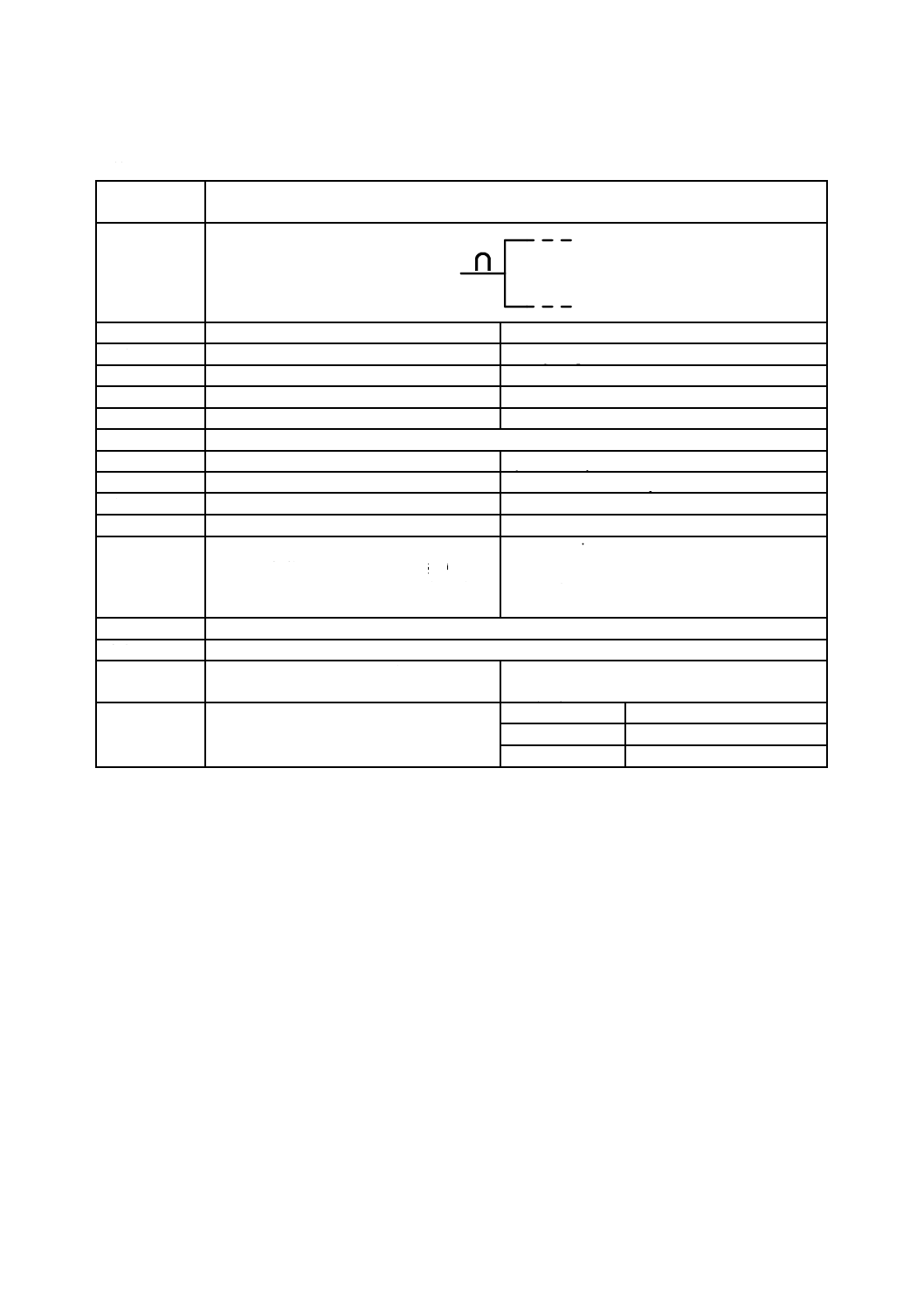
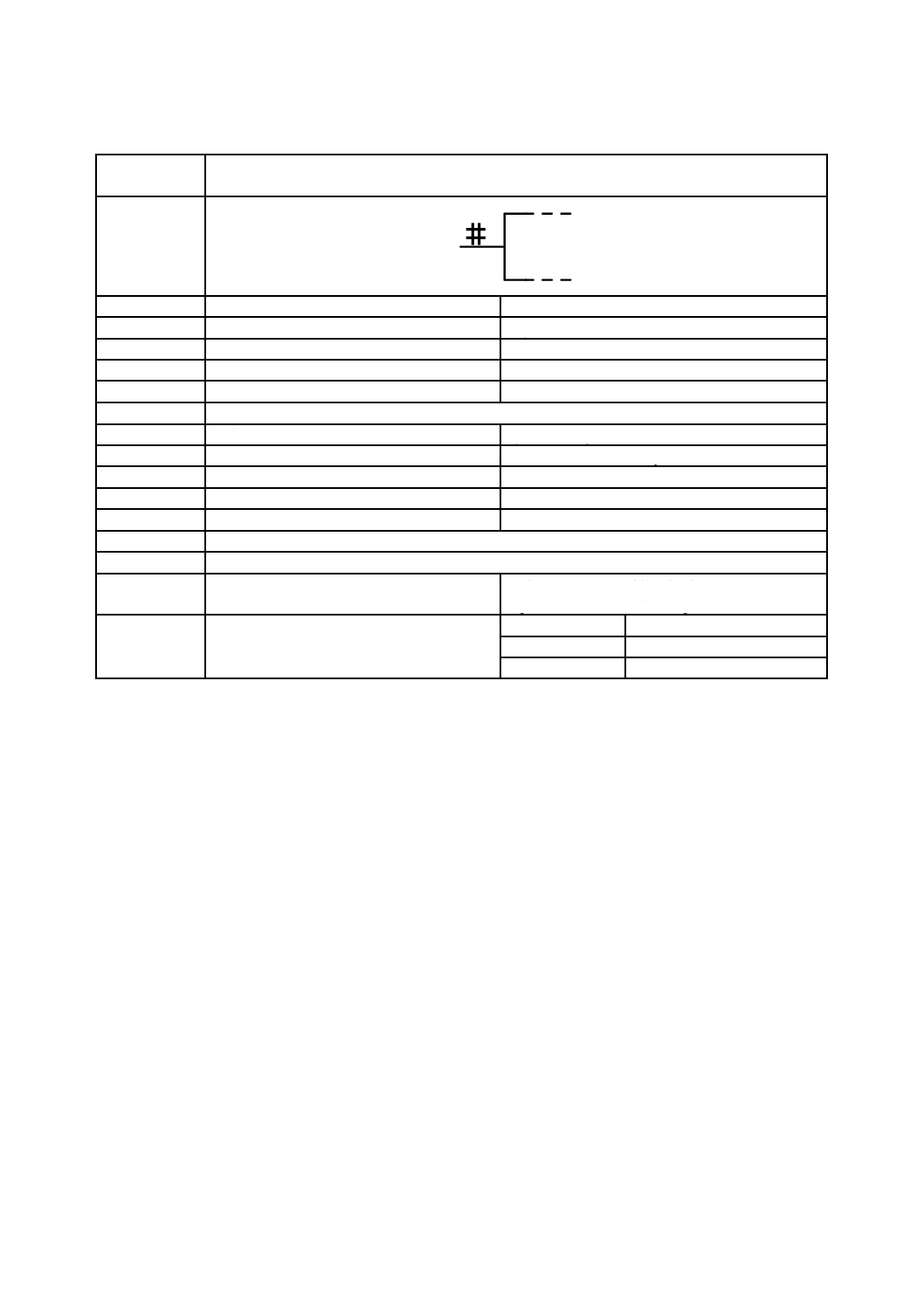
電源電圧供給端子
Supply-voltage terminal
別の名称
−
−
様式
−
−
別様式
13-05-02
S01754
注釈
A00322,A00352
適用分類
限定図記号
Qualifiers only
機能分類
機能属性だけ(-)
- Functional attributes only
形状分類
文字
Characters
制限事項
−
−
補足事項
図記号は,左側の場合を示してある。
Uは,その前に極性符号を付けてもよく,又
は次のもので置き換えてもよい。
− 符号付き公称値(例えば,+5 V)又は
− 適切なニモニック(例えば,VCC,GND)。
電源端子を常に表示するわけではない。
Symbol shown on the left-hand side.
U may be followed by the polarity sign or may be
replaced by
− the nominal signed value (e.g., +5 V) or by
− a suitable mnemonic (e.g., VCC, GND).
Supply terminals are not always shown in a diagram.
適用図記号
S01752
被適用図記号
S01740,S01726,S01725,S01741,S01743,S01742,S01779,S01780,S01790,S01793,S01794,
S01795,S01792,S01803,S01806
キーワード
アナログ回路,演算回路,二進論理回路,接
続,端子
analogue circuits, arithmetic circuits, binary logic
circuits, connections, terminals
注記
−
Status level
Standard
Released on
2004-09-13
Obsolete from
−
12
C 0617-13:2011
2019年7月1日の法改正により名称が変わりました。まえがきを除き,本規格中の「日本工業規格」を「日本産業規格」に読み替えてください。
第5節 入力,出力及び他の接続に関連する限定図記号
図記号番号
(識別番号)
図記号(Symbol)
13-05-02
(S01754)
項目
説明
IEC 60617情報(参考)
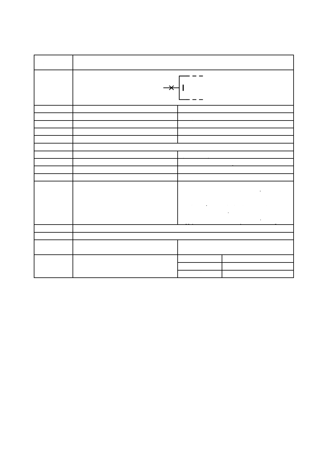
名称
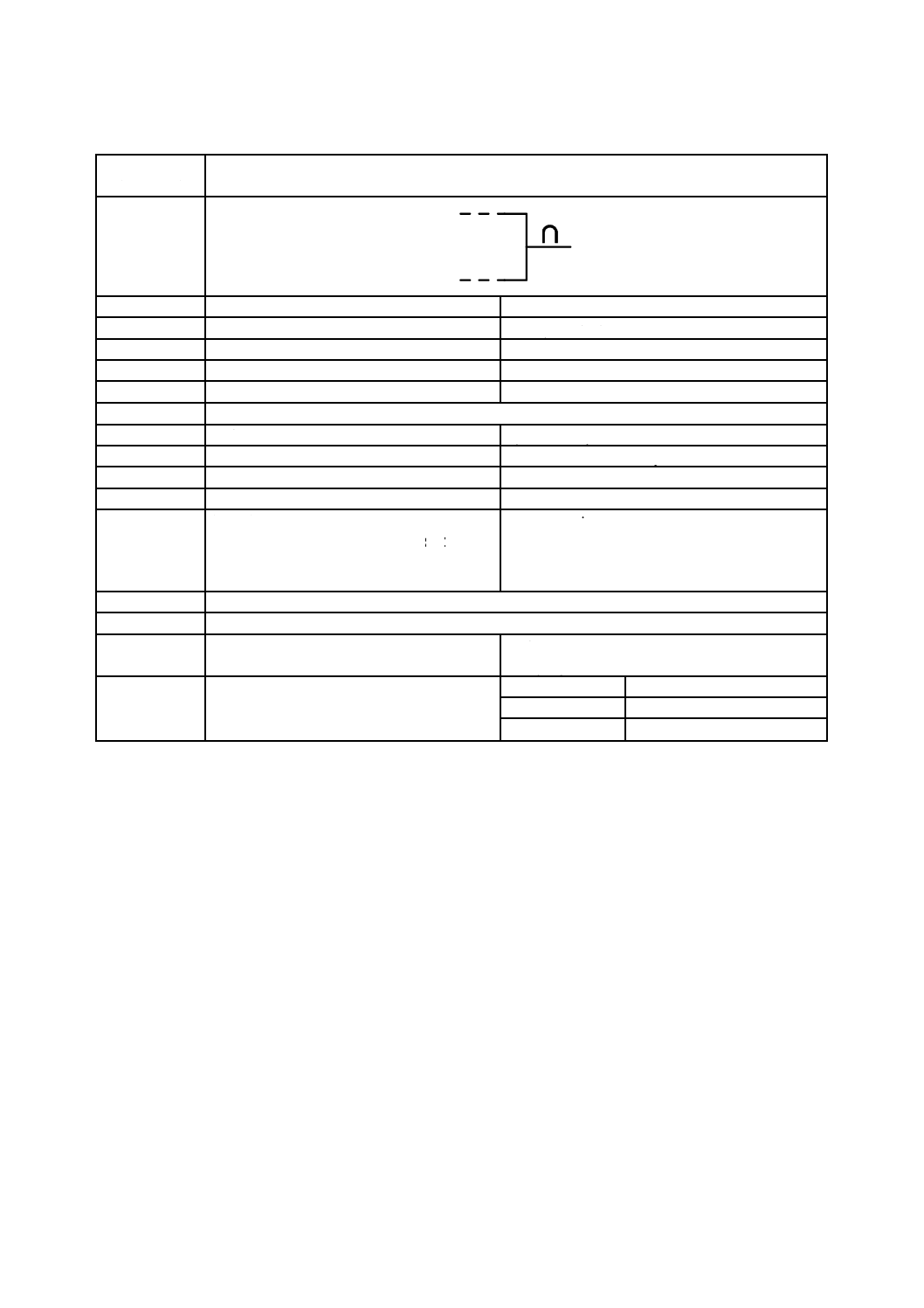
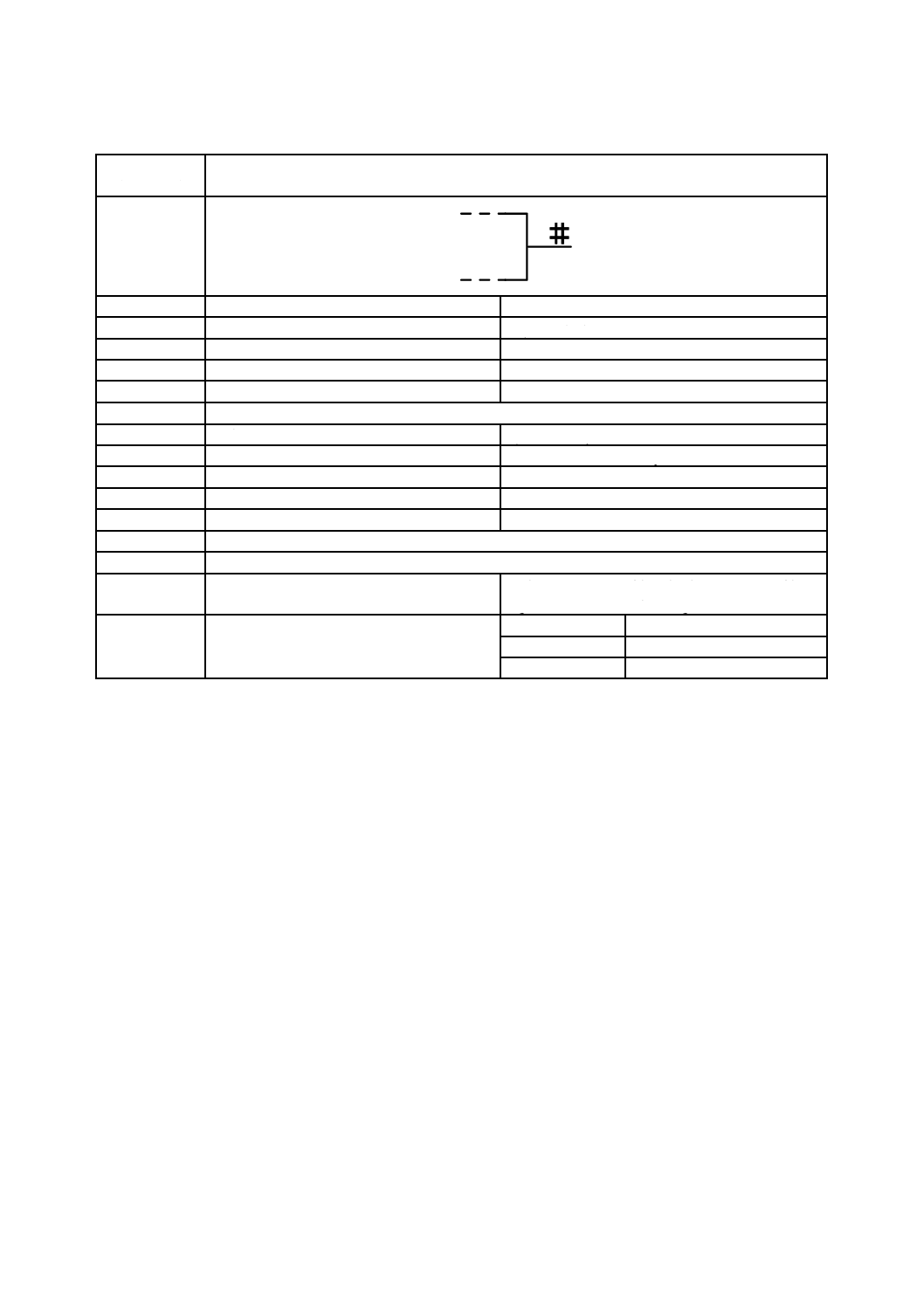
電源電流供給端子
Supply-current terminal
別の名称
−
−
様式
−
−
別様式
13-05-01
S01753
注釈
A00322,A00352
適用分類
限定図記号
Qualifiers only
機能分類
機能属性だけ(-)
- Functional attributes only
形状分類
文字
Characters
制限事項
−
−
補足事項
図記号は,左側の場合を示してある。
Iは,その前に極性符号を付けてもよく,又
は次のもので置き換えてもよい。
− 符号付き公称値(例えば,10 mA)又は
− 適切なニモニック(例えば,VCC,GND)。
電源端子を常に表示するわけではない。
Symbol shown on the left-hand side.
I may be followed by the polarity sign or may be
replaced by
− the nominal signed value (e.g., 10 mA) or by
− a suitable mnemonic (e.g.,VCC, GND).
Supply terminals are not always shown in a diagram.
適用図記号
S01752
被適用図記号
−
キーワード
アナログ回路,演算回路,二進論理回路,接
続,端子
analogue circuits, arithmetic circuits, binary logic
circuits, connections, terminals
注記
−
Status level
Standard
Released on
2004-09-13
Obsolete from
−
13
C 0617-13:2011
2019年7月1日の法改正により名称が変わりました。まえがきを除き,本規格中の「日本工業規格」を「日本産業規格」に読み替えてください。
第5節 入力,出力及び他の接続に関連する限定図記号
図記号番号
(識別番号)
図記号(Symbol)
13-05-03
(S01755)
項目
説明
IEC 60617情報(参考)
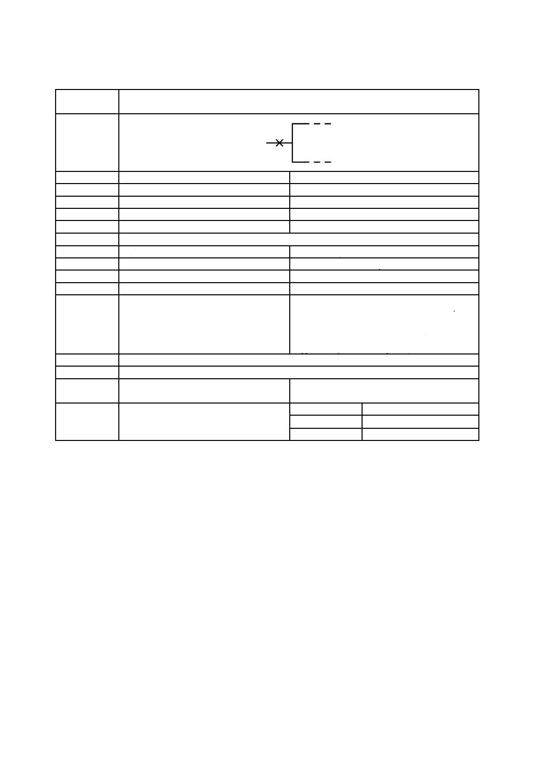
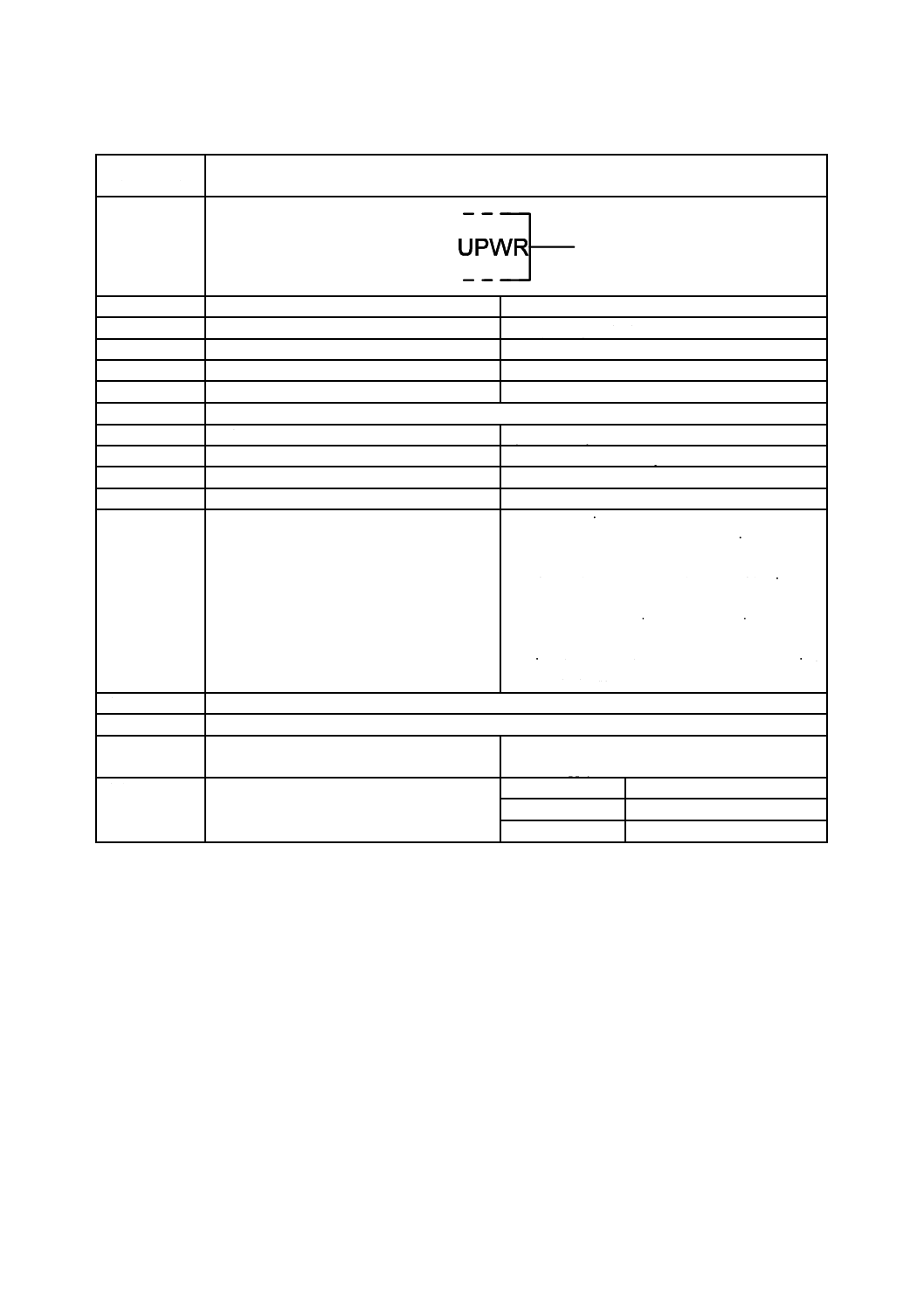
名称
電源電圧出力
Supply-voltage output
別の名称
−
−
様式
−
−
別様式
−
−
注釈
A00322,A00352
適用分類
限定図記号
Qualifiers only
機能分類
機能属性だけ(-)
- Functional attributes only
形状分類
文字
Characters
制限事項
−
−
補足事項
電源の出力。
U[I]は,その前に極性符号を付けてもよく,
又は次のもので置き換えてもよい。
− 符号付き公称値(例えば,+5 V PWR,1
A PWR)又は
− 適切なニモニック(例えば,VCCPWR,
GNDPWR)。
電力出力であることを強調する必要がない
場合,図記号13-05-08(S01760)を用いる。
An output that is a source of power.
U [I] may be followed by the polarity sign or may be
replaced by
− the nominal signed value (e.g.,resulting in +5 V
PWR, 1 A PWR), or by
− a suitable mnemonic (e.g.,resulting in VCCPWR,
GNDPWR).
If it is not necessary to emphasize the fact that it is a
power output, use symbol S01760.
適用図記号
−
被適用図記号
−
キーワード
アナログ回路,演算回路,二進論理回路,電
源回路
analogue circuits, arithmetic circuits, binary logic
circuits, supply circuits
注記
−
Status level
Standard
Released on
2004-09-13
Obsolete from
−

14
C 0617-13:2011
2019年7月1日の法改正により名称が変わりました。まえがきを除き,本規格中の「日本工業規格」を「日本産業規格」に読み替えてください。
第5節 入力,出力及び他の接続に関連する限定図記号
図記号番号
(識別番号)
図記号(Symbol)
13-05-04
(S01756)
項目
説明
IEC 60617情報(参考)
名称
電源電流出力
Supply-current output
別の名称
−
−
様式
−
−
別様式
−
−
注釈
A00322,A00352
適用分類
限定図記号
Qualifiers only
機能分類
機能属性だけ(-)
- Functional attributes only
形状分類
文字
Characters
制限事項
−
−
補足事項
電源の出力。
I[U]は,その前に極性符号を付けてもよく,
又は次のもので置き換えてもよい。
− 符号付き公称値(例えば,+5 V PWR,1
A PWR)又は
− 適切なニモニック(例えば,VCCPWR,
GNDPWR)。
電力出力であることを強調する必要がない
場合,図記号13-05-08(S01760)を用いる。
An output that is a source of power.
I [U] may be followed by the polarity sign or may be
replaced by
− the nominal signed value (e.g., resulting in +5 V
PWR, 1 A PWR), or by
− a suitable mnemonic (e.g., resulting in VCCPWR,
GNDPWR).
If it is not necessary to emphasize the fact that it is a
power output, use symbol S01760.
適用図記号
−
被適用図記号
−
キーワード
アナログ回路,演算回路,二進論理回路,電
源回路
analogue circuits, arithmetic circuits, binary logic
circuits, supply circuits
注記
−
Status level
Standard
Released on
2004-09-13
Obsolete from
−
15
C 0617-13:2011
2019年7月1日の法改正により名称が変わりました。まえがきを除き,本規格中の「日本工業規格」を「日本産業規格」に読み替えてください。
第5節 入力,出力及び他の接続に関連する限定図記号
図記号番号
(識別番号)
図記号(Symbol)
13-05-05
(S01757)
項目
説明
IEC 60617情報(参考)
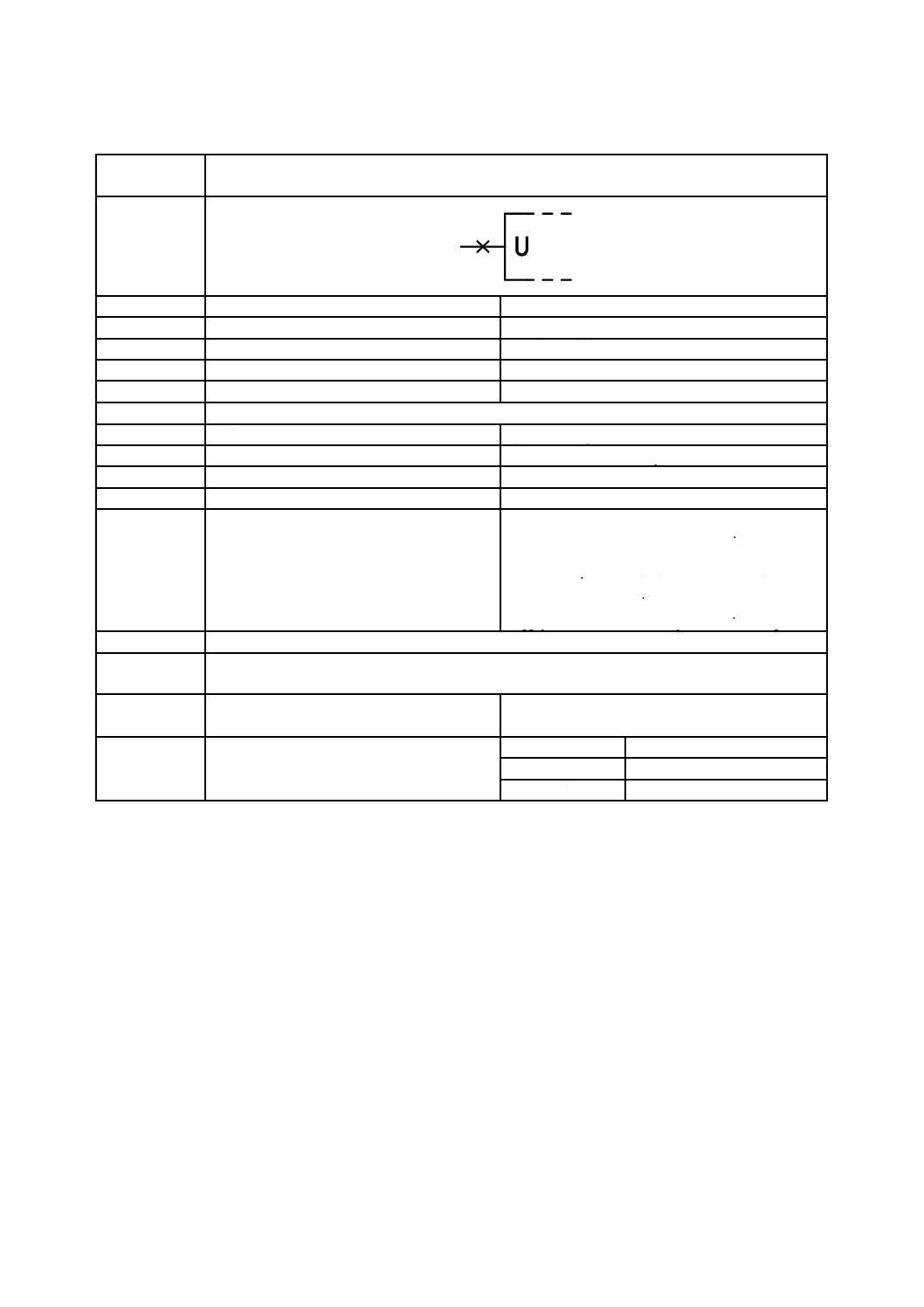
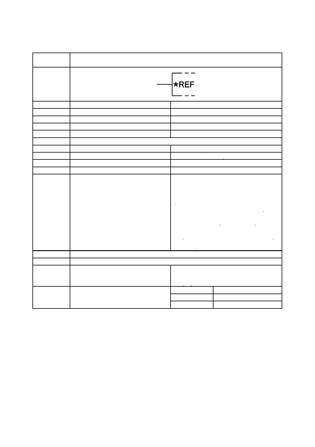
名称
基準入力
Reference input
別の名称
−
−
様式
−
−
別様式
−
−
注釈
A00322,A00352
適用分類
限定図記号
Qualifiers only
機能分類
機能属性だけ(-)
- Functional attributes only
形状分類
文字
Characters
制限事項
−
−
補足事項
基準源に接続する入力。
アスタリスクは,基準量を表す図記号で置き
換えなければならない(例えば,U,I,f,)。
量図記号は,その前に極性符号を付けてもよ
く,又は次のもので置き換えてもよい。
− 符号付き公称値(例えば,+5 V REF,10
mA REF)
− 適切なニモニック(例えば,VCCREF,
GNDREF)
基準入力であることを強調する必要がない
場合,図記号13-05-07(S01759)を用いる。
An input to be connected to a reference source.
The asterisk shall be replaced by the symbol for the
reference quantity (e.g., U, I, f, ).
The quantity symbol may be followed by the polarity
sign or may be replaced by
− the nominal signed value (e.g., resulting in + 5 V
REF, 10 mA REF), or by
− a suitable mnemonic (e.g., resulting in VCCREF,
GNDREF).
If it is not necessary to emphasize the fact that it is a
reference input use symbol S01759.
適用図記号
−
被適用図記号
S01741
キーワード
アナログ回路,アナログ素子,演算回路,演
算素子,二進論理回路,二進論理素子
analogue circuits, analogue elements, arithmetic
circuits, arithmetic elements, binary logic circuits,
binary logic elements
注記
−
Status level
Standard
Released on
2004-09-13
Obsolete from
−

16
C 0617-13:2011
2019年7月1日の法改正により名称が変わりました。まえがきを除き,本規格中の「日本工業規格」を「日本産業規格」に読み替えてください。
第5節 入力,出力及び他の接続に関連する限定図記号
図記号番号
(識別番号)
図記号(Symbol)
13-05-06
(S01758)
項目
説明
IEC 60617情報(参考)
名称
基準出力
Reference output
別の名称
−
−
様式
−
−
別様式
−
−
注釈
A00352
適用分類
限定図記号
Qualifiers only
機能分類
機能属性だけ(-)
- Functional attributes only
形状分類
文字
Characters
制限事項
−
−
補足事項
基準源である出力。
アスタリスクは,基準量を表す図記号で置き
換えなければならない(例えば,U,I,f,)。
量図記号は,その前に極性符号を付けてもよ
く,又は次のもので置き換えてもよい。
− 符号付き公称値(例えば,+5 V REF,10
mA REF)
− 適切なニモニック(例えば,VCCREF,
GNDREF)
基準入力であることを強調する必要がない
場合,図記号13-05-08(S01760)を用いる。
An output that is a reference source.
The asterisk shall be replaced by the symbol for the
reference quantity (e.g., U, I, f, ).
The quantity symbol may be followed by the polarity
sign or may be replaced by
− the nominal signed value (e.g., resulting in + 5 V
REF, 10 mA REF), or by
− a suitable mnemonic (e.g., resulting in VCCREF,
GNDREF).
If it is not necessary to emphasize the fact that it is a
reference output use symbol S01760.
適用図記号
−
被適用図記号
−
キーワード
アナログ回路,アナログ素子,演算回路,演
算素子,二進論理回路,二進論理素子
analogue circuits, analogue elements, arithmetic
circuits, arithmetic elements, binary logic circuits,
binary logic elements
注記
−
Status level
Standard
Released on
2004-09-13
Obsolete from
−
17
C 0617-13:2011
2019年7月1日の法改正により名称が変わりました。まえがきを除き,本規格中の「日本工業規格」を「日本産業規格」に読み替えてください。
第5節 入力,出力及び他の接続に関連する限定図記号
図記号番号
(識別番号)
図記号(Symbol)
13-05-07
(S01759)
項目
説明
IEC 60617情報(参考)
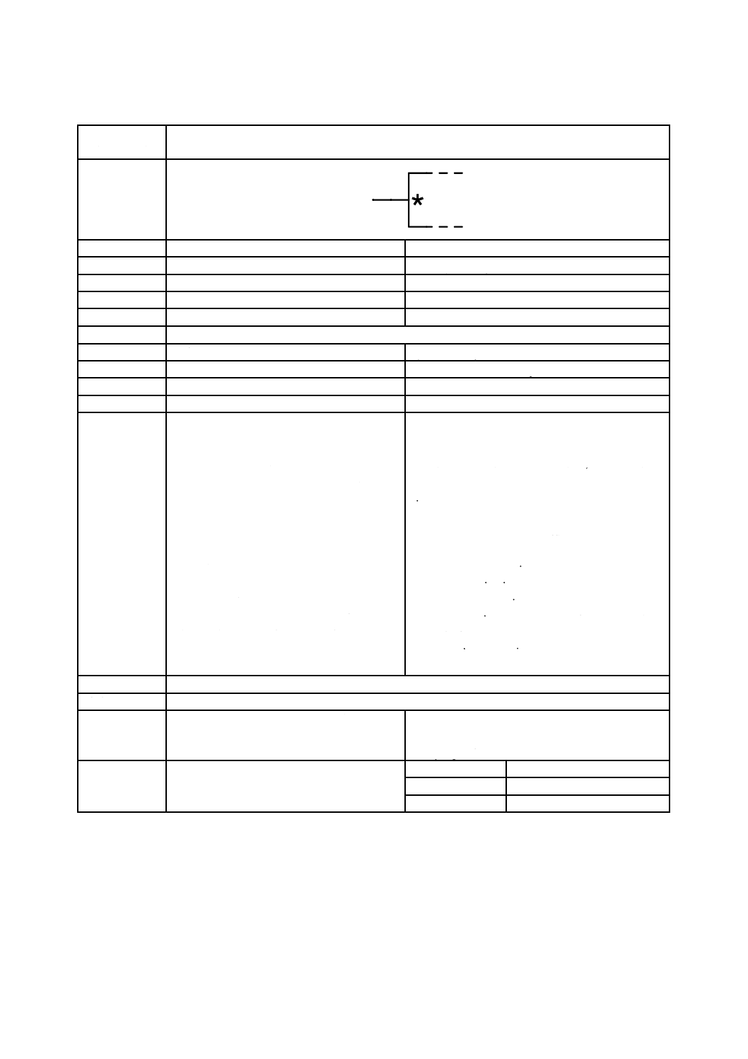
名称
量検出入力
Quantity-sensing input
別の名称
−
−
様式
−
−
別様式
−
−
注釈
A00322,A00352
適用分類
限定図記号
Qualifiers only
機能分類
機能属性だけ(-)
- Functional attributes only
形状分類
文字
Characters
制限事項
−
−
補足事項
入力の情報を表す量を表示する。
アスタリスクは,情報を示す量図記号で置き
換えなければならない(例えば,U,I,f,)。
量図記号は,その前に極性符号を付けてもよ
く,次に示す範囲又はある値で置き換えても
よい:
− 符号付き公称値(例えば,+5 V,0 mA...20
mA,440 Hz)
− 適切なニモニック(例えば,VCC,GND,
A#)
極性符号を示さない場合,混乱を生じるおそ
れがなければ,Uを省略することが望ましい。
この図記号を他の図記号[例えば13-05-09
(S01761)]と組み合わせる場合,他の図記
号に続いて表示することが望ましい。必要で
あれば,この図記号を角括弧でくくる。
Input for which the indicated quantity represents the
information.
The asterisk shall be replaced by the symbol for the
quantity representing the information (e.g., U, I, f, ).
The quantity symbol may be followed by the polarity
sign or may be replaced by one of the following
indications of the range or fixed value:
− a nominal signed value or values (e.g., +5 V, 0
mA...20 mA,440 Hz) or
− a suitable mnemonic (e.g., VCC, GND, A#).
If the polarity sign is not shown, U should be omitted
unless confusion is likely.
If this symbol is combined with other symbols (e.g.,
S01761) it should follow those other symbols,
enclosed, if necessary, in square brackets.
適用図記号
−
被適用図記号
−
キーワード
アナログ回路,アナログ素子,演算回路,演
算素子,二進論理回路,二進論理素子
analogue circuits, analogue elements, arithmetic
circuits, arithmetic elements, binary logic circuits,
binary logic elements
注記
−
Status level
Standard
Released on
2004-09-13
Obsolete from
−

18
C 0617-13:2011
2019年7月1日の法改正により名称が変わりました。まえがきを除き,本規格中の「日本工業規格」を「日本産業規格」に読み替えてください。
第5節 入力,出力及び他の接続に関連する限定図記号
図記号番号
(識別番号)
図記号(Symbol)
13-05-08
(S01760)
項目
説明
IEC 60617情報(参考)
名称
量出力
Quantity output
別の名称
−
−
様式
−
−
別様式
−
−
注釈
A00322,A00352
適用分類
限定図記号
Qualifiers only
機能分類
機能属性だけ(-)
- Functional attributes only
形状分類
文字
Characters
制限事項
−
−
補足事項
出力の情報を表す量を表示する。
アスタリスクは,情報を示す量図記号で置き
換えなければならない(例えば,U,I,f,)。
量図記号は,その前に極性符号を付けてもよ
く,次に示す範囲又はある値で置き換えても
よい。
− 符号付き公称値(例えば,+5 V,0 mA...20
mA,440 Hz)又は
− 適切なニモニック(例えば,VCC,GND,
A#)
極性符号を示さない場合,混乱を生じるおそ
れがなければ,Uを省略することが望ましい。
この図記号を他の図記号[例えば13-05-09
(S01761)]と組み合わせる場合,他の図記
号に続いて表示することが望ましい。必要で
あれば,この図記号を角括弧でくくる。
Output for which the indicated quantity represents the
information.
The asterisk shall be replaced by the symbol for the
quantity representing the information (e.g., U, I, f, ).
The quantity symbol may be followed by the polarity
sign or may be replaced by one of the following
indications of the range or fixed value:
− a nominal signed value or values (e.g., +5 V, 0
mA...20 mA,440 Hz) or
− a suitable mnemonic (e.g., VCC, GND, A#).
If the polarity sign is not shown, U should be omitted
unless confusion is likely.
If this symbol is combined with other symbols (e.g.,
S01761) it should follow those other symbols,
enclosed, if necessary, in square brackets.
適用図記号
−
被適用図記号
−
キーワード
アナログ回路,アナログ素子,演算回路,演
算素子,二進論理回路,二進論理素子
analogue circuits, analogue elements, arithmetic
circuits, arithmetic elements, binary logic circuits,
binary logic elements
注記
−
Status level
Standard
Released on
2004-09-13
Obsolete from
−

19
C 0617-13:2011
2019年7月1日の法改正により名称が変わりました。まえがきを除き,本規格中の「日本工業規格」を「日本産業規格」に読み替えてください。
第5節 入力,出力及び他の接続に関連する限定図記号
図記号番号
(識別番号)
図記号(Symbol)
13-05-09
(S01761)
項目
説明
IEC 60617情報(参考)
名称
アナログオペランド入力
Analogue operand input
別の名称
−
−
様式
−
−
別様式
−
−
注釈
A00322,A00352
適用分類
限定図記号
Qualifiers only
機能分類
機能属性だけ(-)
- Functional attributes only
形状分類
文字
Characters
制限事項
−
−
補足事項
X入力を示してある。
この入力は,一つ以上のアナログ演算のため
のオペランドを表す。
アナログオペランドの場合,文字X及びYを
用いるのが望ましい。二つ以上のオペランド
を使用する場合,他の文字を用いてもよく,
混乱を生じるおそれがなければ,添字を付け
てもよい。
X-input shown.
This input represents an operand on which one or more
analogue functions are performed.
For analogue operands, the letters X and Y should be
used. If more than two operands are involved, other
characters may be used or suffixes may be added,
providing no confusion is likely.
適用図記号
−
被適用図記号
S01779,S01780
キーワード
アナログ回路,アナログ素子
analogue circuits, analogue elements
注記
−
Status level
Standard
Released on
2004-09-13
Obsolete from
−
20
C 0617-13:2011
2019年7月1日の法改正により名称が変わりました。まえがきを除き,本規格中の「日本工業規格」を「日本産業規格」に読み替えてください。
第5節 入力,出力及び他の接続に関連する限定図記号
図記号番号
(識別番号)
図記号(Symbol)
13-05-10
(S01762)
項目
説明
IEC 60617情報(参考)
名称
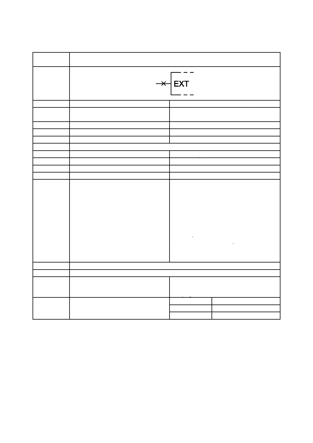
補助回路又は補助回路素子と外部接続する
端子
Terminal to be externally connected to a subsidiary
circuit or circuit element
別の名称
−
−
様式
−
−
別様式
−
−
注釈
A00322,A00352
適用分類
限定図記号
Qualifiers only
機能分類
機能属性だけ(-)
- Functional attributes only
形状分類
文字
Characters
制限事項
−
−
補足事項
左側の場合を示してある。
EXTは,他の表示で置き換えることが望まし
い。例えば,
RX 抵抗
CX キャパシタ(コンデンサ)
RCX 抵抗器及びキャパシタ(コンデンサ)
XTAL 水晶振動子
混乱を生じるおそれがなければ,この図記号
を補助接続図記号[図記号13-04-05(S01752)]
なしで表示してもよい。
極性表示が必要な場合,+又は−を,この図
記号に添字として付けてもよい。
Shown on the left-hand side.
EXT should be replaced by another designation, e.g.,
RX resistance
CX capacitance
RCX resistance and capacitance
XTAL crystal
This symbol may be shown without the symbol for
subsidiary connection (symbol S01752) if no
confusion is likely.
If an indication of the polarity is necessary, a + or a−
may be added as a suffix to the symbol.
適用図記号
S01752
被適用図記号
−
キーワード
アナログ回路,アナログ素子,演算回路,演
算素子,二進論理回路,二進論理素子
analogue circuits, analogue elements, arithmetic
circuits, arithmetic elements, binary logic circuits,
binary logic elements
注記
−
Status level
Standard
Released on
2004-09-13
Obsolete from
−
21
C 0617-13:2011
2019年7月1日の法改正により名称が変わりました。まえがきを除き,本規格中の「日本工業規格」を「日本産業規格」に読み替えてください。
第5節 入力,出力及び他の接続に関連する限定図記号
図記号番号
(識別番号)
図記号(Symbol)
13-05-11
(S01763)
項目
説明
IEC 60617情報(参考)
名称
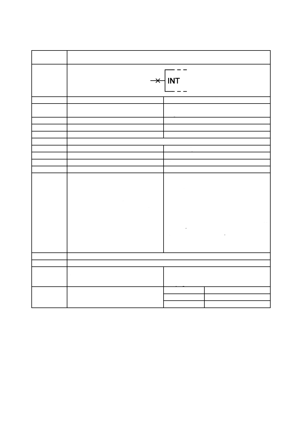
内部にある補助回路又は回路構成部分の端
子
Terminal of a subsidiary internal circuit or circuit
component
別の名称
−
−
様式
−
−
別様式
−
−
注釈
A00322,A00352
適用分類
限定図記号
Qualifiers only
機能分類
機能属性だけ(-)
- Functional attributes only
形状分類
文字
Characters
制限事項
−
−
補足事項
左側の場合を示してある。
INTは,他の表示で置き換えることが望まし
い。例えば,
RINT 抵抗
CINT キャパシタ(コンデンサ)
RCINT 抵抗器及びキャパシタ(コンデンサ)
XTALINT 水晶振動子
混乱を生じるおそれがなければ,この図記号
を補助接続図記号[図記号13-04-05(S01752)]
なしで表示してもよい。
極性表示が必要な場合,+又は−を,この図
記号に添字として付けてもよい。
Shown on the left-hand side.
INT should be replaced by another designation, e.g.,
RINT resistance
CINT capacitance
RCINT resistance and capacitance
XTALINT crystal
This symbol may be shown without the symbol for
subsidiary connection (symbol S01752) if no
confusion is likely.
If an indication of the polarity is necessary, a + or a−
may be added as a suffix to the symbol.
適用図記号
S01752
被適用図記号
−
キーワード
アナログ回路,アナログ素子,演算回路,演
算素子,二進論理回路,二進論理素子
analogue circuits, analogue elements, arithmetic
circuits, arithmetic elements, binary logic circuits,
binary logic elements
注記
−
Status level
Standard
Released on
2004-09-13
Obsolete from
−
22
C 0617-13:2011
2019年7月1日の法改正により名称が変わりました。まえがきを除き,本規格中の「日本工業規格」を「日本産業規格」に読み替えてください。
第5節 入力,出力及び他の接続に関連する限定図記号
図記号番号
(識別番号)
図記号(Symbol)
13-05-12
(S01764)
項目
説明
IEC 60617情報(参考)
名称
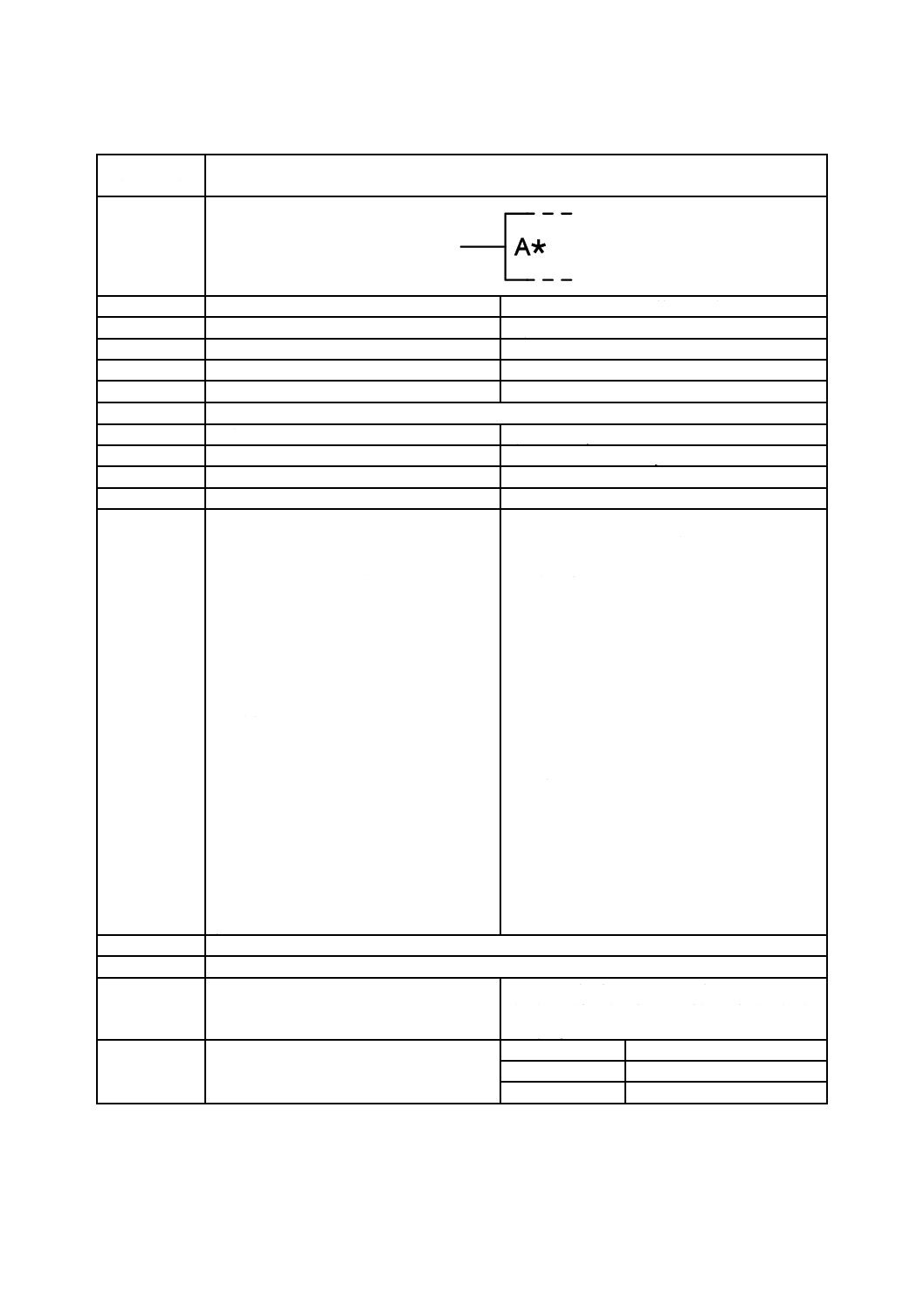
調整端子
Adjustment terminal
別の名称
−
−
様式
−
−
別様式
−
−
注釈
A00322,A00352
適用分類
限定図記号
Qualifiers only
機能分類
機能属性だけ(-)
- Functional attributes only
形状分類
文字
Characters
制限事項
−
−
補足事項
左側の場合を示してある。
A*をADJで置き換えなければならないか,又
はアスタリスクだけを,調整を要する特性若
しくは量の表示で置き換えなければならな
い。
次に示す特性又は量に対しては,次の表示を
使用することが望ましい。
B−バイアス
CL−電流制限
f−周波数
m−増幅
H−ヒステリシス
OFS−オフセット
P−電力
SR−スルーレート
SYM−対称
T−温度
U又はV−電圧
WF−波形
Z−インピーダンス
φ−位相
Shown on the left-hand side.
The A* shall be replaced by ADJ, or only the asterisk
shall be replaced by an indication of the property or
quantity to be adjusted.
The following indications should be used for the
properties or quantities listed:
B−bias
CL−current limit
f−frequency
m−amplification
H−hysteresis
OFS−offset
P−power
SR−slew rate
SYM−symmetry
T−temperature
U or V−voltage
WF−waveform
Z−impedance
φ−phase
適用図記号
−
被適用図記号
S01602,S01779,S01784,S01780,S01783,S01787,S01786,S01785,S01788,S01794,S01799
キーワード
アナログ回路,アナログ素子,演算回路,演
算素子,二進論理回路,二進論理素子
analogue circuits, analogue elements, arithmetic
circuits, arithmetic elements, binary logic circuits,
binary logic elements
注記
−
Status level
Standard
Released on
2004-09-13
Obsolete from
−
23
C 0617-13:2011
2019年7月1日の法改正により名称が変わりました。まえがきを除き,本規格中の「日本工業規格」を「日本産業規格」に読み替えてください。
第5節 入力,出力及び他の接続に関連する限定図記号
図記号番号
(識別番号)
図記号(Symbol)
13-05-13
(S01765)
項目
説明
IEC 60617情報(参考)
名称
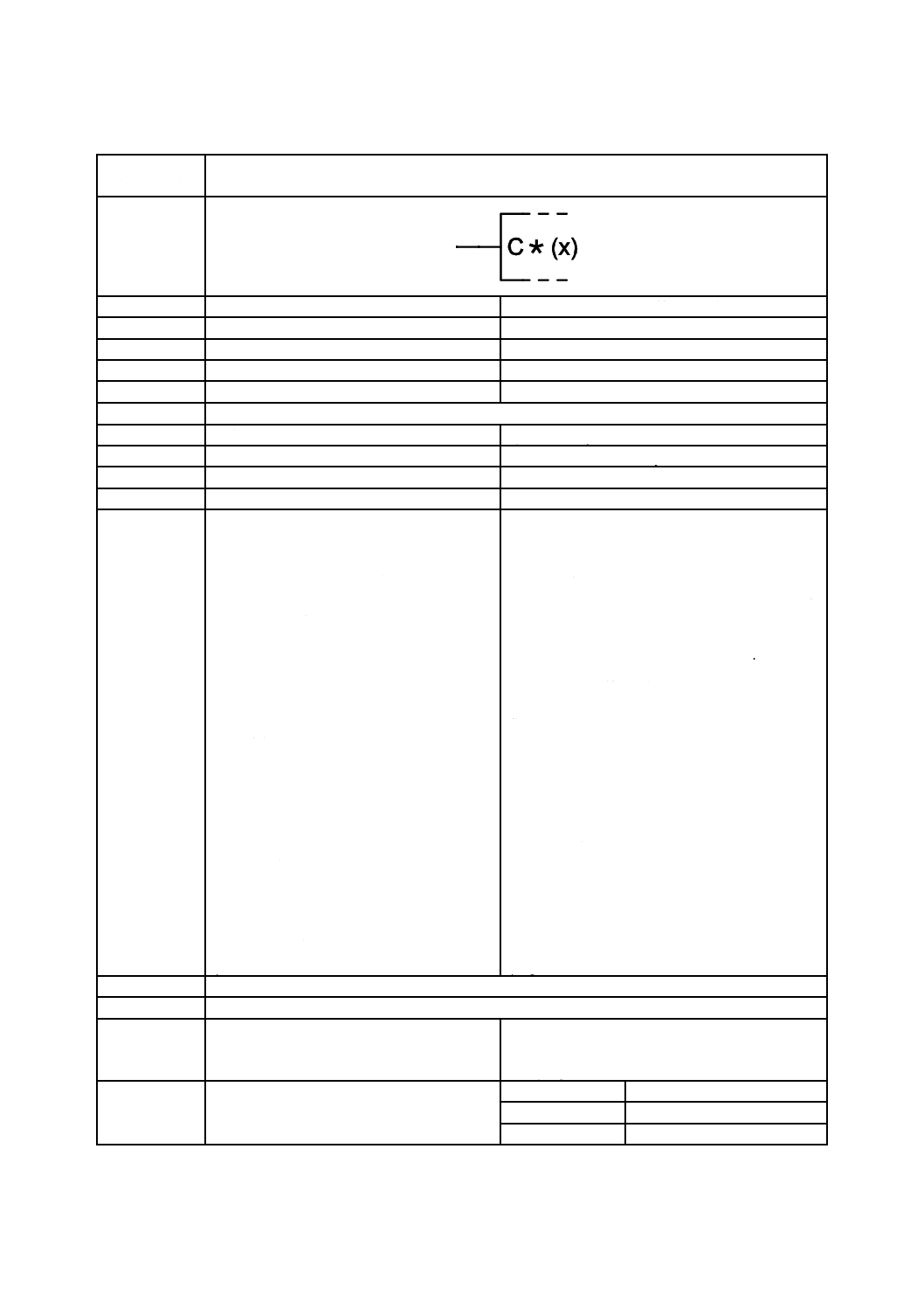
補償端子
Compensation terminal
別の名称
−
−
様式
−
−
別様式
−
−
注釈
A00322,A00352
適用分類
限定図記号
Qualifiers only
機能分類
機能属性だけ(-)
- Functional attributes only
形状分類
文字
Characters
制限事項
−
−
補足事項
左側の場合を示してある。
C*をCPNで置き換えなければならないか,
又はアスタリスクだけを,調整を要する特性
若しくは量の表示で置き換えなければなら
ない。
xを調整又は補償を要する特性若しくは量の
表示で置き換えなければならない。
アスタリスク及び/又はxと置き換える表示
は,次の表示を使用することが望ましい。
B−バイアス
CL−電流制限
f−周波数
H−ヒステリシス
m−増幅
OFS−オフセット
P−電力
SR−スルーレート
SYM−対称
T−温度
U又はV−電圧
WF−波形
Z−インピーダンス
φ−位相
Shown on the left-hand side.
The C* shall be replaced by CPN, or only the asterisk
shall be replaced by an indication of the property or
quantity to be adjusted.
The x shall be replaced by an indication of the property
or quantity that causes the adjustment or compensation
to be necessary.
The following indications should be used in replacing
the asterisk and/ or the x:
B−bias;
CL−current limit;
f−frequency;
H−hysteresis;
m−amplification;
OFS−offset;
P−power;
SR−slew rate;
SYM−symmetry;
T−temperature;
U or V−voltage;
WF−waveform;
Z−impedance;
φ−phase.
適用図記号
−
被適用図記号
S01784,S01787,S01786,S01790,S01794,S01803
キーワード
アナログ回路,アナログ素子,演算回路,演
算素子,二進論理回路,二進論理素子
analogue circuits, analogue elements, arithmetic
circuits, arithmetic elements, binary logic circuits,
binary logic elements
注記
−
Status level
Standard
Released on
2004-09-13
Obsolete from
−
24
C 0617-13:2011
2019年7月1日の法改正により名称が変わりました。まえがきを除き,本規格中の「日本工業規格」を「日本産業規格」に読み替えてください。
第5節 入力,出力及び他の接続に関連する限定図記号
図記号番号
(識別番号)
図記号(Symbol)
13-05-14
(S01766)
項目
説明
IEC 60617情報(参考)
名称
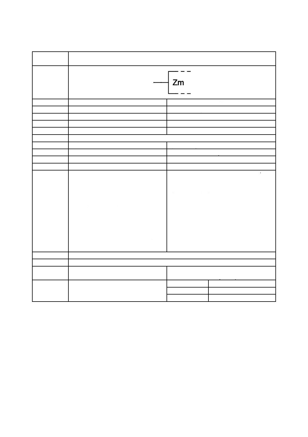
Zm入力(入力インピーダンス)(アナログ) Zm-input (analogue)
別の名称
−
−
様式
−
−
別様式
−
−
注釈
A00276,A00289,A00322,A00352
適用分類
限定図記号
Qualifiers only
機能分類
機能属性だけ(-)
- Functional attributes only
形状分類
文字
Characters
制限事項
−
−
補足事項
アナログの影響Zm入力又はZm出力の影響
を受けるアナログ入力及びアナログ出力の
信号レベルが,この影響入力(出力)に強制
的に反映される。
これらの図記号は,“m”を関連する識別番号
で置き換えることを含む依存関係表記の応
用を示す。
ここで採用している方法についての説明は,
注釈A00276及びA00289を参照する。
ディジタルの影響Zm入力及びZm出力につ
いては,図記号12-17-01(S01554)を参照す
る。
Affecting analogue Zm-inputs or Zm-outputs impose
their signal levels on the analogue inputs and outputs
affected by them.
These symbols imply the application of dependency
notation including the replacement of "m" by the
relevant identifying number.
For an explanation of the techniques involved, see
A00276 and A00289.
For affecting digital Zm-inputs and Zm-outputs, see
S01554.
適用図記号
S01554
被適用図記号
−
キーワード
アナログ素子,依存関係表記,相互接続依存 analogue
elements,
dependency
notation,
INTERCONNECTION dependency
注記
−
Status level
Standard
Released on
2004-09-13
Obsolete from
−
25
C 0617-13:2011
2019年7月1日の法改正により名称が変わりました。まえがきを除き,本規格中の「日本工業規格」を「日本産業規格」に読み替えてください。
第5節 入力,出力及び他の接続に関連する限定図記号
図記号番号
(識別番号)
図記号(Symbol)
13-05-15
(S01767)
項目
説明
IEC 60617情報(参考)
名称
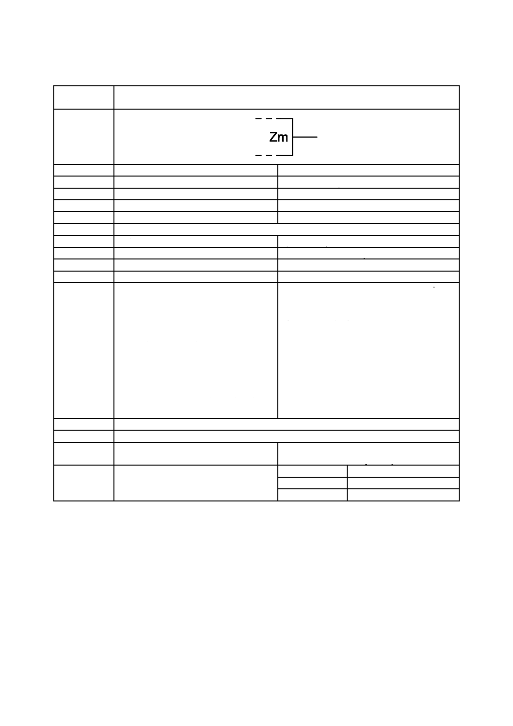
Zm出力(出力インピーダンス)(アナログ) Zm-output (analogue)
別の名称
−
−
様式
−
−
別様式
−
−
注釈
A00276,A00289,A00322,A00352
適用分類
限定図記号
Qualifiers only
機能分類
機能属性だけ(-)
- Functional attributes only
形状分類
文字
Characters
制限事項
−
−
補足事項
アナログの影響Zm入力又はZm出力の影響
を受けるアナログ入力及びアナログ出力の
信号レベルが,この影響入力(出力)に強制
的に反映される。
これらの図記号は,“m”を関連する識別番号
で置き換えることを含む依存関係表記の応
用を示す。
ここで採用している方法についての説明は,
A00276及びA00289を参照する。
ディジタルの影響Zm入力及びZm出力につ
いては,図記号12-17-02(S01555)を参照す
る。
Affecting analogue Zm-inputs or Zm-outputs impose
their signal levels on the analogue inputs and outputs
affected by them.
These symbols imply the application of dependency
notation including the replacement of "m" by the
relevant identifying number.
For an explanation of the techniques involved, see
A00276 and S00289.
For affecting digital Zm-inputs and Zm-outputs, see
S01555.
適用図記号
S01555
被適用図記号
−
キーワード
アナログ素子,依存関係表記,相互接続依存 analogue
elements,
dependency
notation,
INTERCONNECTION dependency
注記
−
Status level
Standard
Released on
2004-09-13
Obsolete from
−
26
C 0617-13:2011
2019年7月1日の法改正により名称が変わりました。まえがきを除き,本規格中の「日本工業規格」を「日本産業規格」に読み替えてください。
第5節 入力,出力及び他の接続に関連する限定図記号
図記号番号
(識別番号)
図記号(Symbol)
13-05-16
(S01768)
項目
説明
IEC 60617情報(参考)
名称
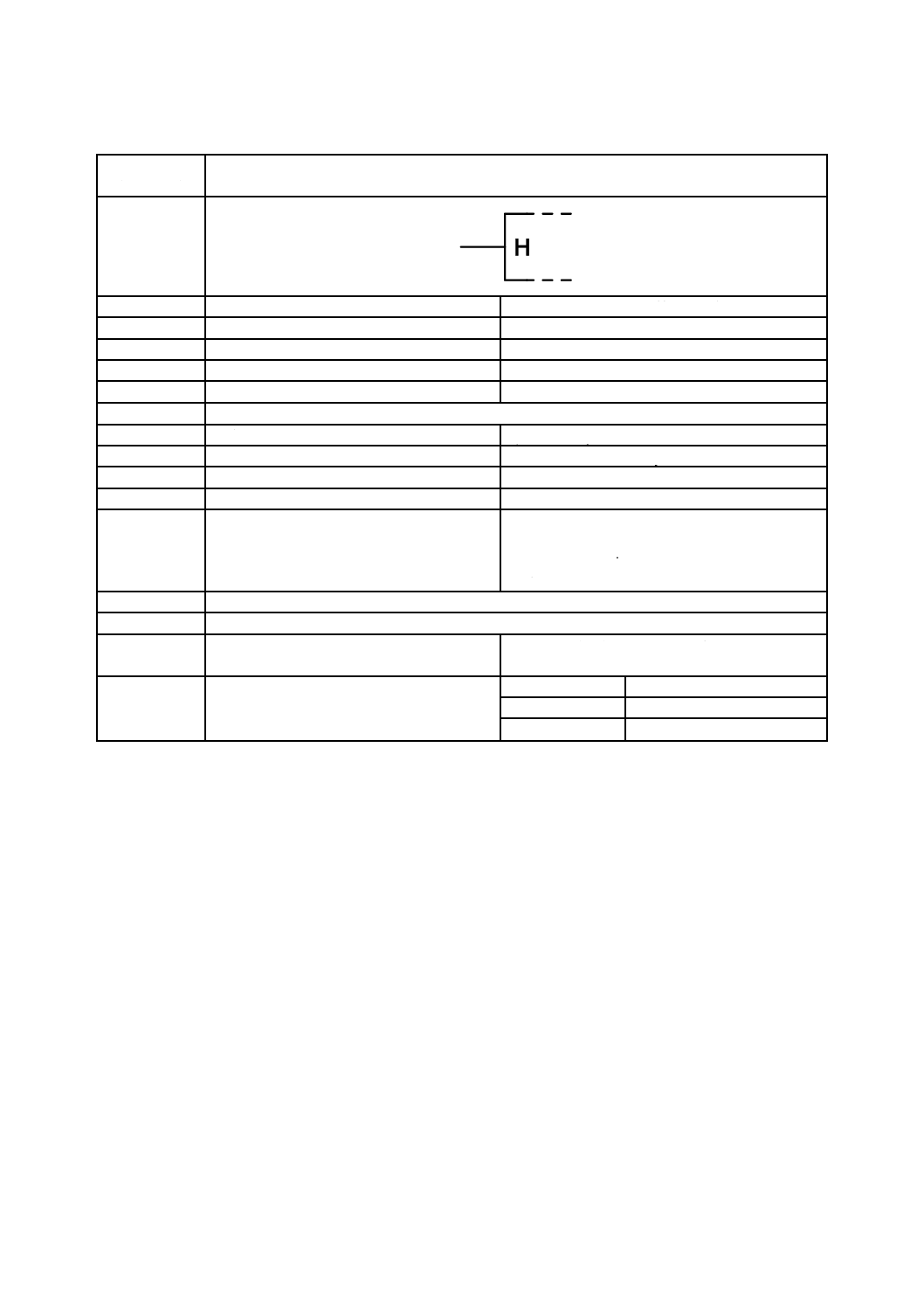
保持入力
Hold input
別の名称
−
−
様式
−
−
別様式
−
−
注釈
A00321,A00322,A00352,A00353
適用分類
限定図記号
Qualifiers only
機能分類
機能属性だけ(-)
- Functional attributes only
形状分類
文字
Characters
制限事項
−
−
補足事項
この入力が内部状態1になると,アナログ出
力が自己の値を保持する。
この入力が内部状態0であるとき,素子に影
響を及ぼさない。
When this input takes on its internal 1-state, the
analogue outputs hold their values.
When this input is in its internal 0-state, it has no effect
on the element.
適用図記号
−
被適用図記号
S01787,S01789
キーワード
アナログ回路,アナログ素子,演算回路,演
算素子
analogue circuits, analogue elements, arithmetic
circuits, arithmetic elements
注記
−
Status level
Standard
Released on
2004-09-13
Obsolete from
−
27
C 0617-13:2011
2019年7月1日の法改正により名称が変わりました。まえがきを除き,本規格中の「日本工業規格」を「日本産業規格」に読み替えてください。
第5節 入力,出力及び他の接続に関連する限定図記号
図記号番号
(識別番号)
図記号(Symbol)
13-05-17
(S01769)
項目
説明
IEC 60617情報(参考)
名称
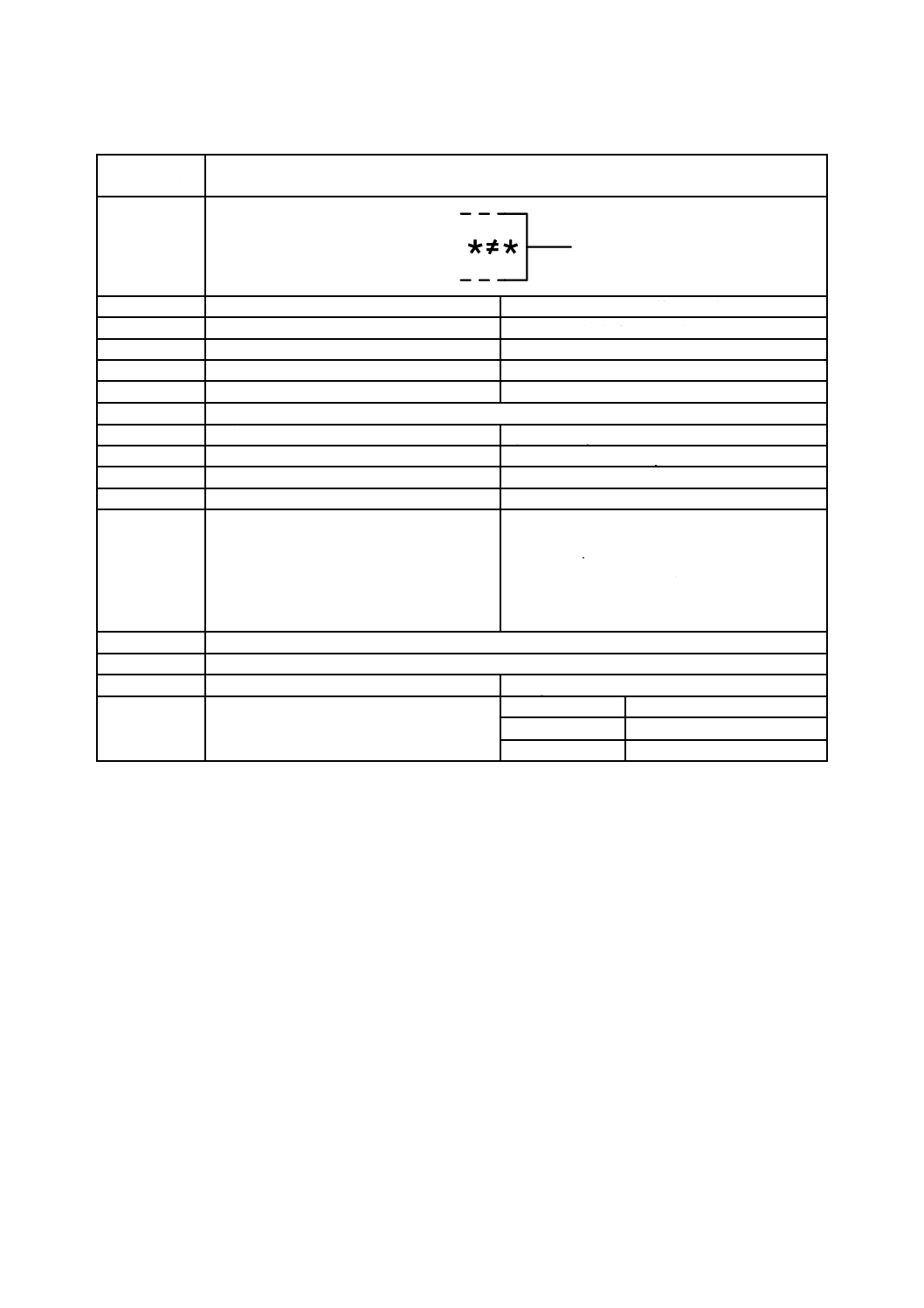
比較器(不等値出力)
Not-equal output of a comparator
別の名称
−
−
様式
−
−
別様式
−
−
注釈
A00321,A00322,A00352,A00353
適用分類
限定図記号
Qualifiers only
機能分類
機能属性だけ(-)
- Functional attributes only
形状分類
文字
Characters
制限事項
−
−
補足事項
アスタリスクは,比較される量又はオペラン
ドの表示で置き換えなければならない。
図記号は,JIS C 0456“に不等”の文字3/6
として定義されている。JIS X 0221“NOT
EQUAL TO”のUCS 2260(表77)と同等で
ある。
The asterisks shall be replaced by designations of the
quantities or operands whose values are compared.
The symbol is defined as character 3/6 of IEC 61286
"NOT EQUAL TO", equivalent to UCS 2260 (Table
60) of ISO/IEC 10646 "NOT EQUAL TO".
適用図記号
−
被適用図記号
−
キーワード
アナログ素子
analogue elements
注記
−
Status level
Standard
Released on
2004-09-13
Obsolete from
−

28
C 0617-13:2011
2019年7月1日の法改正により名称が変わりました。まえがきを除き,本規格中の「日本工業規格」を「日本産業規格」に読み替えてください。
第5節 入力,出力及び他の接続に関連する限定図記号
図記号番号
(識別番号)
図記号(Symbol)
13-05-18
(S01770)
項目
説明
IEC 60617情報(参考)
名称
比較器(>より大出力)
Greater-than output of a comparator
別の名称
−
−
様式
−
−
別様式
−
−
注釈
A00321,A00322,A00352,A00353
適用分類
限定図記号
Qualifiers only
機能分類
機能属性だけ(-)
- Functional attributes only
形状分類
文字
Characters
制限事項
−
−
補足事項
アスタリスクは,比較される量又はオペラン
ドの表示で置き換えなければならない。
The asterisks shall be replaced by designations of the
quantities or operands whose values are compared.
適用図記号
S01523
被適用図記号
S01699,S01700,S01721,S01802,S01801
キーワード
アナログ素子
analogue elements
注記
−
Status level
Standard
Released on
2004-09-13
Obsolete from
−

29
C 0617-13:2011
2019年7月1日の法改正により名称が変わりました。まえがきを除き,本規格中の「日本工業規格」を「日本産業規格」に読み替えてください。
第5節 入力,出力及び他の接続に関連する限定図記号
図記号番号
(識別番号)
図記号(Symbol)
13-05-19
(S01771)
項目
説明
IEC 60617情報(参考)
名称
比較器[<(より小)出力]
Less-than output of a comparator
別の名称
−
−
様式
−
−
別様式
−
−
注釈
A00321,A00322,A00352,A00353
適用分類
限定図記号
Qualifiers only
機能分類
機能属性だけ(-)
- Functional attributes only
形状分類
文字
Characters
制限事項
−
−
補足事項
アスタリスクは,比較される量又はオペラン
ドの表示で置き換えなければならない。
The asterisks shall be replaced by designations of the
quantities or operands whose values are compared.
適用図記号
S01524
被適用図記号
S01721
キーワード
アナログ素子
analogue elements
注記
−
Status level
Standard
Released on
2004-09-13
Obsolete from
−
30
C 0617-13:2011
2019年7月1日の法改正により名称が変わりました。まえがきを除き,本規格中の「日本工業規格」を「日本産業規格」に読み替えてください。
第5節 入力,出力及び他の接続に関連する限定図記号
図記号番号
(識別番号)
図記号(Symbol)
13-05-20
(S01772)
項目
説明
IEC 60617情報(参考)
名称
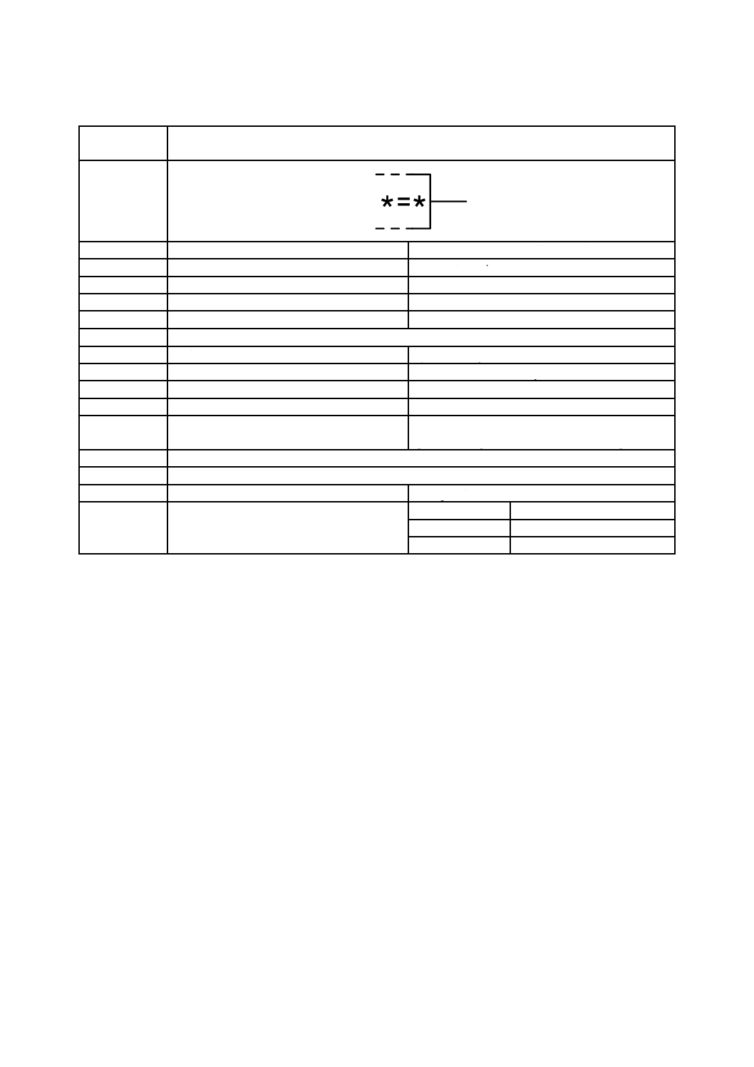
比較器(=等値 出力)
Equal output of a comparator
別の名称
−
−
様式
−
−
別様式
−
−
注釈
A00321,A00322,A00352,A00353
適用分類
限定図記号
Qualifiers only
機能分類
機能属性だけ(-)
- Functional attributes only
形状分類
文字
Characters
制限事項
−
−
補足事項
アスタリスクは,比較される量又はオペラン
ドの表示で置き換えなければならない。
The asterisks shall be replaced by designations of the
quantities or operands whose values are compared.
適用図記号
S01525
被適用図記号
S01699,S01701,S01719,S01721
キーワード
アナログ素子
analogue elements
注記
−
Status level
Standard
Released on
2004-09-13
Obsolete from
−
31
C 0617-13:2011
2019年7月1日の法改正により名称が変わりました。まえがきを除き,本規格中の「日本工業規格」を「日本産業規格」に読み替えてください。
第5節 入力,出力及び他の接続に関連する限定図記号
図記号番号
(識別番号)
図記号(Symbol)
13-05-21
(S01773)
項目
説明
IEC 60617情報(参考)
名称
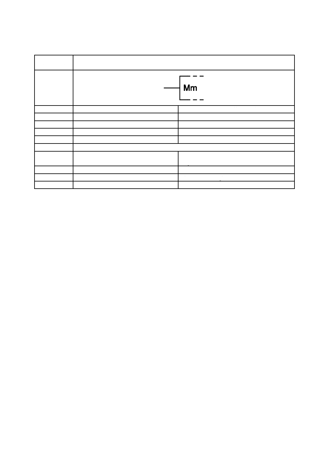
Mm入力
Mm-input
別の名称
−
−
様式
−
−
別様式
−
−
注釈
A00276,A00289,A00321,A00352,A00353
適用分類
回路図,機能図,概要図
Circuit diagrams, Function diagrams, Overview
diagrams
機能分類
信号又は情報の処理(K)
K Processing signals or information
形状分類
文字,長方形
Characters, Rectangles
制限事項
−
−
32
C 0617-13:2011
2019年7月1日の法改正により名称が変わりました。まえがきを除き,本規格中の「日本工業規格」を「日本産業規格」に読み替えてください。
補足事項
この図記号は,“m”を関連する識別番号で置
き換えることを含む依存関係表記の応用を
示す。
ここで採用している方法についての説明は,
A00276及びA00289を参照する。
Mm入力[Mm出力]の内部状態が1ならば,
このMm入力[Mm出力]の影響を受ける全
ての入力は,通常定義された素子の機能どお
りに働く。また,このMm入力[Mm出力]
によって影響を受ける全ての出力は,通常定
義された内部論理状態又はアナログ信号値
となる。すなわち,入力と出力は,イネイブ
ル状態となる。
Mm入力[Mm出力]の内部状態が0ならば,
入力と出力に対するその影響は次のように
なる。
− このMm入力[Mm出力]によって影響
を受ける全ての入力は素子の機能に対し
て何も作用しない。
− 影響を受ける入力に,斜線によって区切
られたラベルの幾つかの組が割り付けて
あれば,そのMm入力[Mm出力]の識
別子を含む組は無効となり,無視しなけ
ればならない。これは,多機能入力の一
部の機能が停止することを意味する。
− このMm入力[Mm出力]によって影響
を受ける出力では,Mm入力[Mm出力]
の識別子を含む全てのラベルの組は何も
作用せず,無視しなければならない。
− 影響を受ける出力に,斜線によって区切
られたラベルの幾つかの組が割り付けて
あれば(注釈A00289を参照),このMm
入力[Mm出力]の識別子を含む組は無
効となり,無視しなければならない。こ
れは,多機能出力のある機能の無効化又
は選択,特性若しくは依存関係の変更を
意味する。
This symbol imply the application of dependency
notation including the replacement of "m" by the
relevant identifying number.
For an explanation of the techniques involved, see
A00276 and A00289.
If an Mm-input [Mm-output] stands at its internal
1-state, any input affected by this Mm-input
[Mm-output] has its normally defined effect on the
function of the element, and any output affected by this
Mminput [Mm-output] stands at its normally defined
internal logic state or analogue signal level. That is, the
inputs and outputs are enabled.
If an Mm-input [Mm-output] stands at its internal
0-state, its effect on inputs and outputs is as follows:
− Any input affected by this Mm-input [Mm-output]
has no effect on the function of the element.
− If an affected input has several sets of labels
separated by solidi, any set containing the
identifying number of the Mm-input [Mm-output]
has no effect and is to be ignored. This represents
disabling some of the functions of a
multi-function input.
− At each output affected by this Mm-input
[Mm-output], any set of labels containing the
identifying number of that Mm-input [Mm-output]
has no effect and is to be ignored.
− If an output has several sets of labels separated by
solidi (see A00289), any set containing the
identifying number of this Mm-input [Mm-output]
is to be ignored. This represents disabling or
selecting some of the functions of a multi-function
output, or modifying some of the characteristics or
dependent relationships of the output.
適用図記号
−
被適用図記号
S01775,S01790
キーワード
アナログ素子,依存関係表記,モード依存
analogue elements, dependency notation, MODE
dependency
注記
−
Status level
Standard
Released on
2004-09-13
Obsolete from
−

33
C 0617-13:2011
2019年7月1日の法改正により名称が変わりました。まえがきを除き,本規格中の「日本工業規格」を「日本産業規格」に読み替えてください。
第5節 入力,出力及び他の接続に関連する限定図記号
図記号番号
(識別番号)
図記号(Symbol)
13-05-22
(S01774)
項目
説明
IEC 60617情報(参考)
名称
Mm出力
Mm-output
別の名称
−
−
様式
−
−
別様式
−
−
注釈
A00276,A00289,A00321,A00352,A00353
適用分類
概念要素又は限定子だけ
Qualifiers only
機能分類
機能属性だけ(-)
- Functional attributes only
形状分類
文字
Characters
制限事項
−
−

34
C 0617-13:2011
2019年7月1日の法改正により名称が変わりました。まえがきを除き,本規格中の「日本工業規格」を「日本産業規格」に読み替えてください。
補足事項
これらの図記号は,“m”を関連する識別番号
で置き換えることを含む依存関係表記の応
用を示す。
ここで採用している方法についての説明は,
A00276及びA00289を参照する。
Mm入力[Mm出力]の内部状態が1ならば,
このMm入力[Mm出力]の影響を受ける全
ての入力は,通常定義された素子の機能どお
りに働く。また,このMm入力[Mm出力]
によって影響を受ける全ての出力は,通常定
義された内部論理状態又はアナログ信号値
となる。すなわち,入力と出力は,イネイブ
ル状態となる。
Mm入力[Mm出力]の内部状態が0ならば,
入力と出力に対するその影響は次のように
なる。
− このMm入力[Mm出力]によって影響
を受ける全ての入力は素子の機能に対し
て何も作用しない。
− 影響を受ける入力に,斜線によって区切
られたラベルの幾つかの組が割り付けて
あれば,そのMm入力[Mm出力]の識
別子を含む組は無効となり,無視しなけ
ればならない。これは,多機能入力の一
部の機能が停止することを意味する。
− このMm入力[Mm出力]によって影響
を受ける出力では,Mm入力[Mm出力]
の識別子を含む全てのラベルの組は何も
作用せず,無視しなければならない。
− 影響を受ける出力に,斜線によって区切
られたラベルの幾つかの組が割り付けて
あれば[JIS C 0617-12の第25節(注釈
A00289)を参照],このMm入力[Mm
出力]の識別子を含む組は無効となり,
無視しなければならない。これは,多機
能出力のある機能の無効化又は選択,特
性若しくは依存関係の変更を意味する。
This symbol imply the application of dependency
notation including the replacement of "m" by the
relevant identifying number.
For an explanation of the techniques involved, see
A00276 and A00289.
If an Mm-input [Mm-output] stands at its internal
1-state, any input affected by this Mm-input
[Mm-output] has its normally defined effect on the
function of the element, and any output affected by this
Mminput [Mm-output] stands at its normally defined
internal logic state or analogue signal level. That is, the
inputs and outputs are enabled.
If an Mm-input [Mm-output] stands at its internal
0-state, its effect on inputs and outputs is as follows:
− Any input affected by this Mm-input [Mm-output]
has no effect on the function of the element.
− If an affected input has several sets of labels
separated by solidi, any set containing the
identifying number of the Mm-input [Mm-output]
has no effect and is to be ignored. This represents
disabling some of the functions of a
multi-function input.
− At each output affected by this Mm-input
[Mm-output],any set of labels containing the
identifying number of that Mm-input [Mm-output]
has no effect and is to be ignored.
− If an output has several sets of labels separated by
solidi (see IEC 617-12,Section 25), any set
containing the identifying number of this
Mm-input [Mm-output] is to be ignored. This
represents disabling or selecting some of the
functions of a multi-function output, or modifying
some of the characteristics or dependent
relationships of the output.
適用図記号
−
被適用図記号
−
キーワード
アナログ素子,依存関係表記,モード依存
analogue elements, dependency notation, MODE
dependency
注記
−
Status level
Standard
Released on
2004-09-13
Obsolete from
−
35
C 0617-13:2011
2019年7月1日の法改正により名称が変わりました。まえがきを除き,本規格中の「日本工業規格」を「日本産業規格」に読み替えてください。
第5節 入力,出力及び他の接続に関連する限定図記号
図記号番号
(識別番号)
図記号(Symbol)
13-05-23
(S01775)
項目
説明
IEC 60617情報(参考)
名称
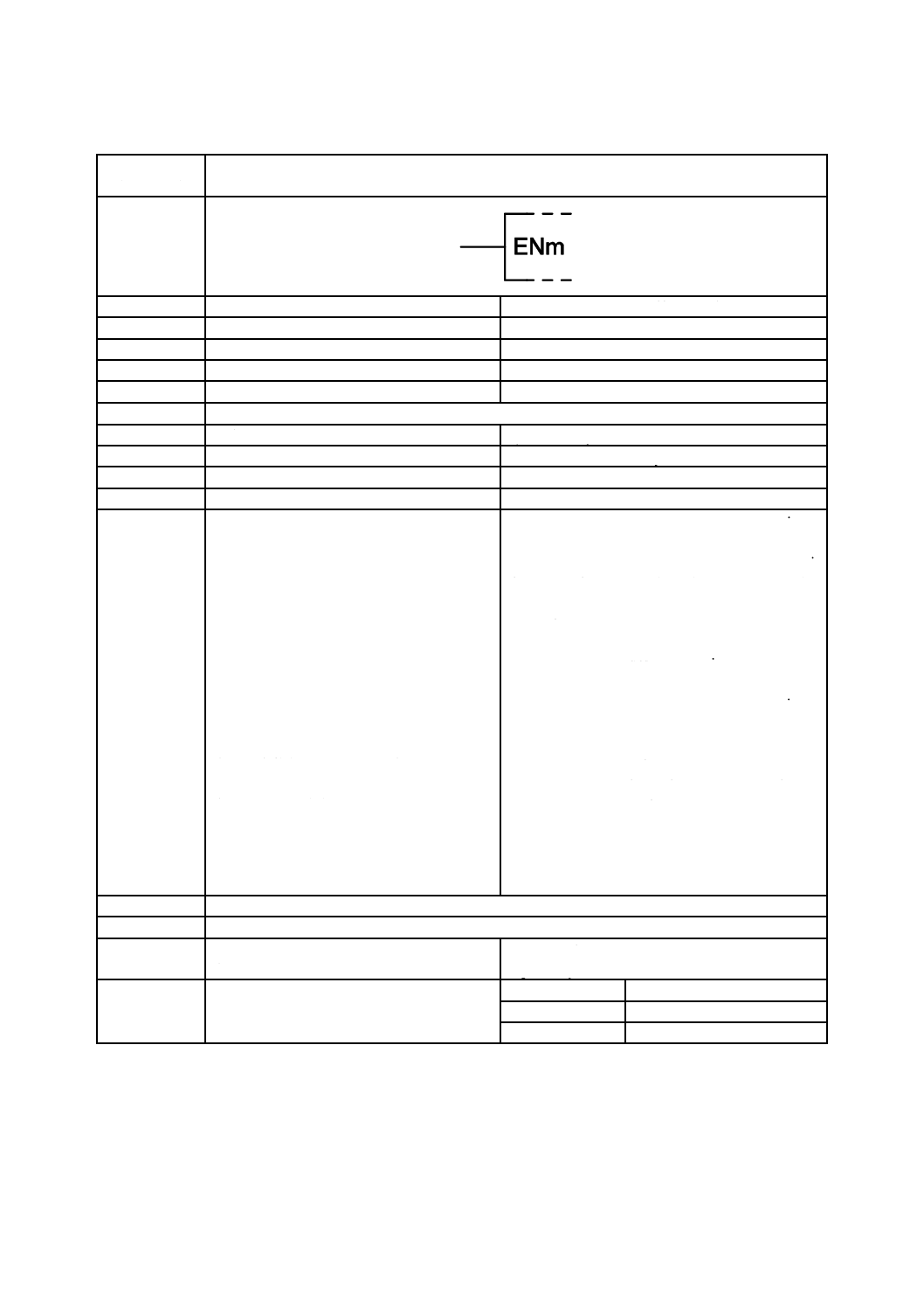
ENm入力
ENm-input
別の名称
−
−
様式
−
−
別様式
−
−
注釈
A00276,A00289,A00321,A00352,A00353
適用分類
限定図記号
Qualifiers only
機能分類
機能属性だけ(-)
- Functional attributes only
形状分類
文字
Characters
制限事項
−
−
補足事項
この入力が被影響出力に与える影響は,Mm
入力の場合と同じである[図記号13-05-21
(S01773)を参照]。
この入力がディジタル被影響出力に与える
影響は,EN入力の場合と同じである[図記
号12-09-11(S01503)を参照]。
アナログ被影響出力に対しては,ENm入力が
内部状態1ならば,出力は通常定義された機
能及びアナログ信号レベルを保つ。ENm入力
が内部状態1でないならば,この図記号では
機能も信号レベルも規定されていない。
ENm入力が図記号12-09-11(S01503)の補足
事項で定義付けされている全ての出力に影
響を及ぼし,入力には影響を及ぼさない場
合,識別番号(m)を省略してもよい。
これらの図記号は,“m”を関連する識別番号
で置き換えることを含む依存関係表記の応
用を示す。ここで採用している方法について
の説明は,A00276及びA00289を参照する。
The effect of this input on its affected inputs is the
same as that of an Mm-input (see symbol S01773).
The effect of this input on its affected digital outputs is
the same as that of an EN-input (see symbol S01503).
For any affected analogue output, if the ENm-input
stands at its internal 1-state, the output has its normally
defined function and analogue signal level. Otherwise,
neither the function nor the level is specified by the
symbol.
If the ENm-input affects all outputs as defined in the
note to symbol S01503,and no inputs, the identifying
numbers (m) may be omitted.
This symbol implies the application of dependency
notation including the replacement of "m" by the
relevant identifying number. For an explanation of the
techniques involved, see A00276 and A00289.
適用図記号
S01503,S01773
被適用図記号
−
キーワード
アナログ素子,依存関係表記,イネーブル依
存
analogue elements, dependency notation, ENABLE
dependency
注記
−
Status level
Standard
Released on
2004-09-13
Obsolete from
−
36
C 0617-13:2011
2019年7月1日の法改正により名称が変わりました。まえがきを除き,本規格中の「日本工業規格」を「日本産業規格」に読み替えてください。
第5節 入力,出力及び他の接続に関連する限定図記号
図記号番号
(識別番号)
図記号(Symbol)
13-05-24
(S01776)
項目
説明
IEC 60617情報(参考)
名称
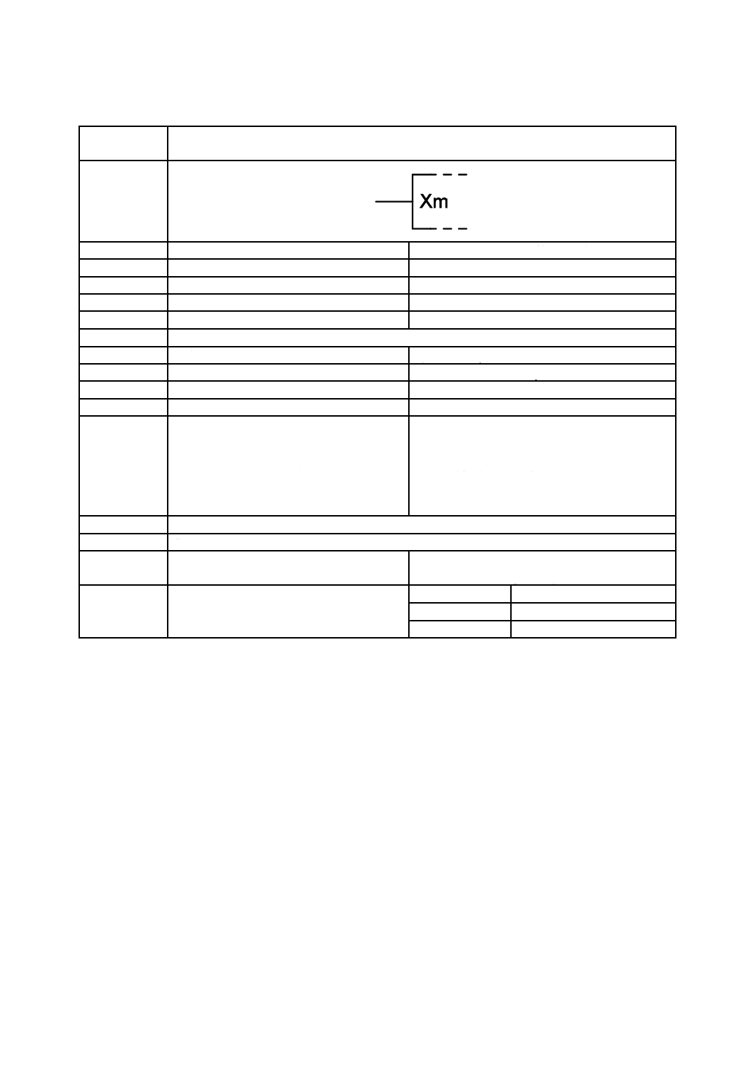
Xm入力
Xm-input
別の名称
−
−
様式
−
−
別様式
−
−
注釈
A00321,A00352,A00353
適用分類
限定図記号
Qualifiers only
機能分類
機能属性だけ(-)
- Functional attributes only
形状分類
文字
Characters
制限事項
−
−
補足事項
図記号12-17A-01(S01556)及び注釈A00281
も参照する。
この図記号は,“m”を関連する識別番号で置
き換えることを含む依存関係表記の応用を
示す。ここで採用している方法についての説
明は,注釈A00276及びA00289を参照する。
See also symbol S01556 and application note A00281.
This symbol implies the application of dependency
notation including the replacement of "m" by the
relevant identifying number. For an explanation of the
techniques involved, see A00276 and A00289.
適用図記号
S01556
被適用図記号
S01804
キーワード
アナログ素子,依存関係表記,伝達依存
analogue
elements,
dependency
notation,
TRANSMISSION dependency
注記
−
Status level
Standard
Released on
2004-09-13
Obsolete from
−

37
C 0617-13:2011
2019年7月1日の法改正により名称が変わりました。まえがきを除き,本規格中の「日本工業規格」を「日本産業規格」に読み替えてください。
第5節 入力,出力及び他の接続に関連する限定図記号
図記号番号
(識別番号)
図記号(Symbol)
13-05-25
(S01777)
項目
説明
IEC 60617情報(参考)
名称
Xm出力
Xm-output
別の名称
−
−
様式
−
−
別様式
−
−
注釈
A00276,A00281,A00289,A00321,A00352,A00353
適用分類
限定図記号
Qualifiers only
機能分類
機能属性だけ(-)
- Functional attributes only
形状分類
文字
Characters
制限事項
−
−
補足事項
図記号12-17A-02(S01557)及び注釈A00281
も参照する。この図記号は,“m”を関連する
識別番号で置き換えることを含む依存関係
表記の応用を示す。ここで採用している方法
についての説明は,注釈A00276及びA00289
を参照する。
See also symbol S01557 and application note A00281.
This symbol implies the application of dependency
notation including the replacement of "m" by the
relevant identifying number. For an explanation of the
techniques involved, see A00276 and A00289.
適用図記号
S01557
被適用図記号
−
キーワード
依存関係表記
dependency notation
注記
−
Status level
Standard
Released on
2004-09-13
Obsolete from
−
38
C 0617-13:2011
2019年7月1日の法改正により名称が変わりました。まえがきを除き,本規格中の「日本工業規格」を「日本産業規格」に読み替えてください。
第III章 算術演算機能を果たす素子
第6節 総則
図記号番号
(識別番号)
図記号(Symbol)
13-06-01
(S01778)
項目
説明
IEC 60617情報(参考)
名称
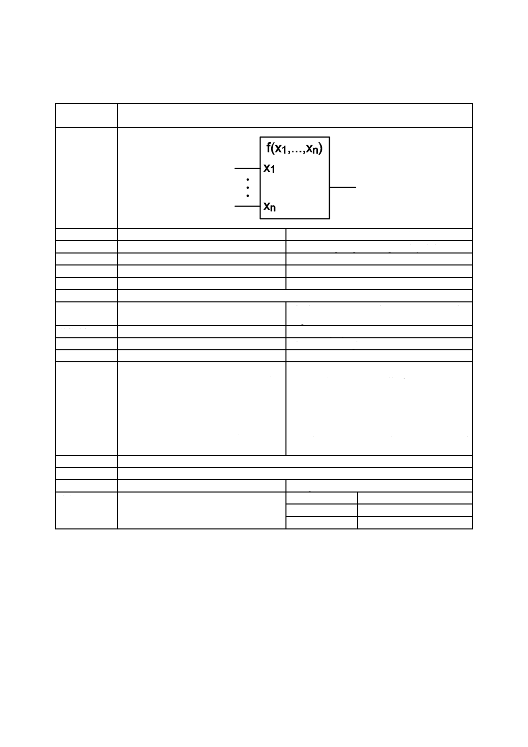
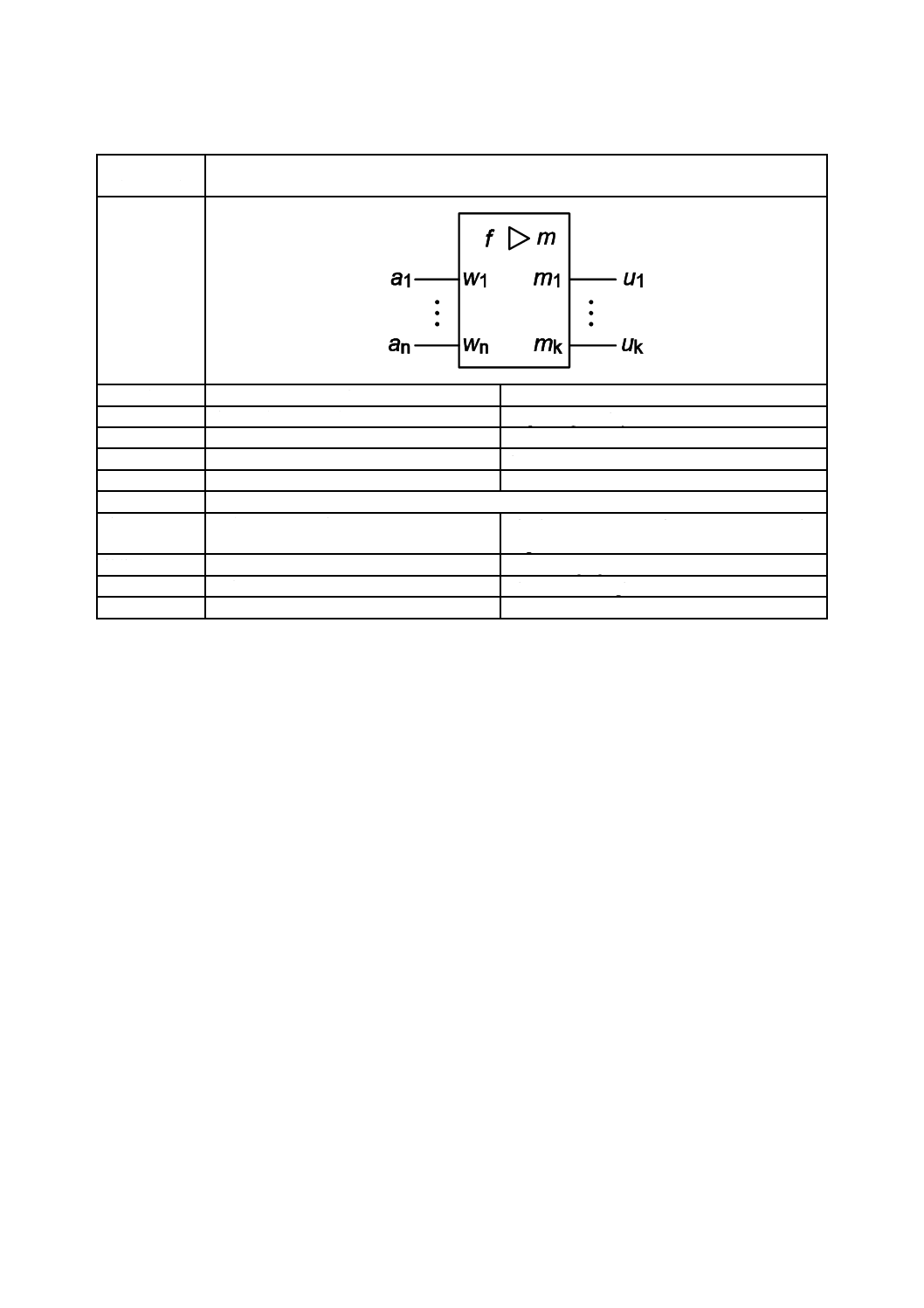
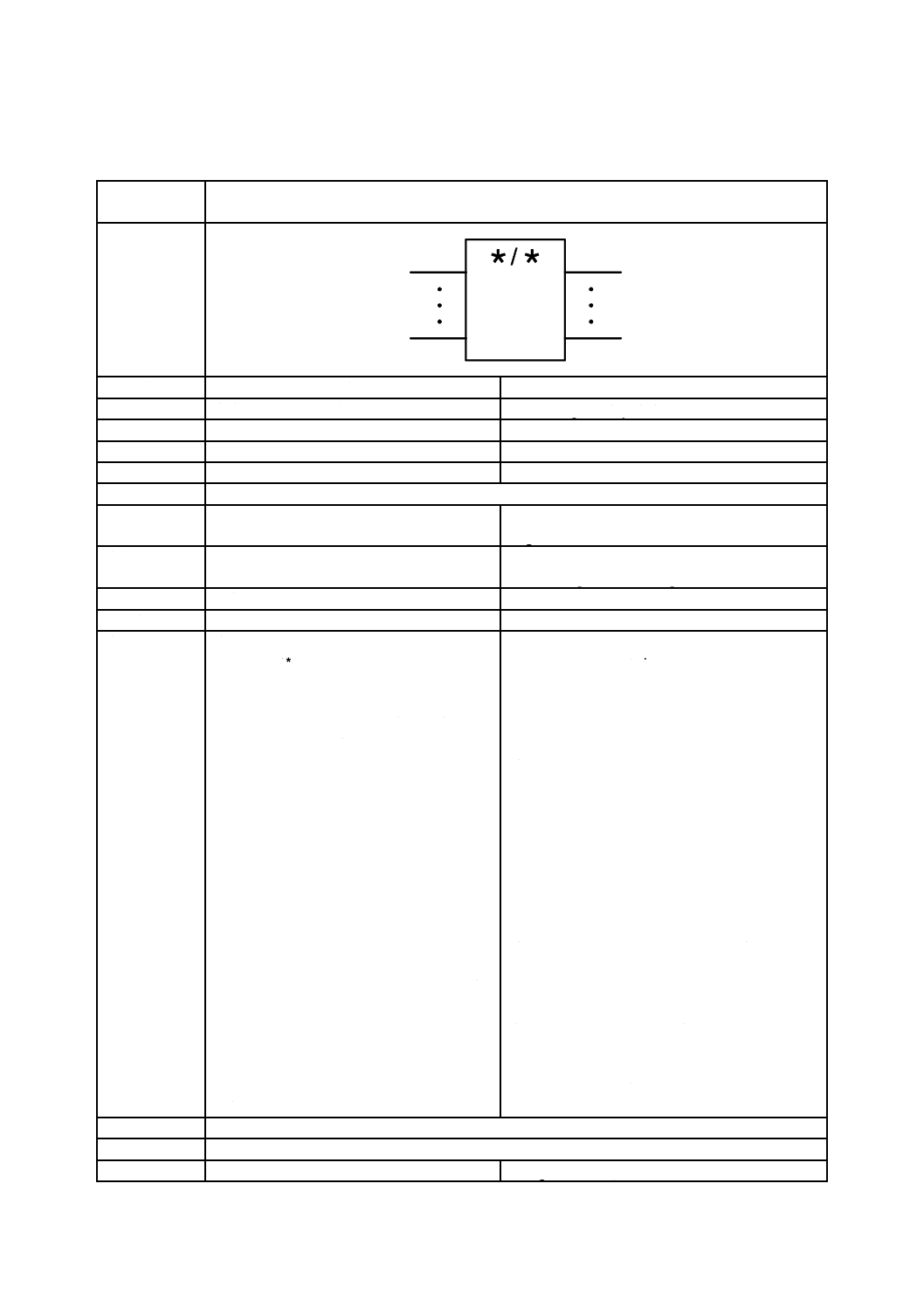
算術演算機能素子(一般図記号)
Function-computing element, general symbol
別の名称
−
−
様式
−
−
別様式
−
−
注釈
A00323,A00352
適用分類
回路図,機能図,概要図
Circuit diagrams, Function diagrams, Overview
diagrams
機能分類
信号又は情報の処理(K)
K Processing signals or information
形状分類
文字,長方形
Characters, Rectangles
制限事項
−
−
補足事項
f (x1, ..., xn) は,関数の適切な表示(図記号又
はグラフ)又は関数の適切な引用で置き換え
なければならない。
x1, ..., xnは,関数の引数の適切な表示で置き
換えなければならない。
レベル変換器の図記号と符号変換器の図記
号の曖昧さを避けるために,斜線を用いて区
分してはならない。
f (x1, ..., xn) shall be replaced by an appropriate
indication (a symbol or a graph) of, or reference to, the
function (see e.g., IEC 27-1).
x1, ..., xn shall be replaced by appropriate indications
of the arguments of the function.
To avoid ambiguity with the symbols for level
converter and the code converter, the solidus shall not
be used to indicate division.
適用図記号
S01463
被適用図記号
S01779,S01780,S01792
キーワード
アナログ素子,演算素子
analogue elements, arithmetic elements
注記
−
Status level
Standard
Released on
2004-09-13
Obsolete from
−
39
C 0617-13:2011
2019年7月1日の法改正により名称が変わりました。まえがきを除き,本規格中の「日本工業規格」を「日本産業規格」に読み替えてください。
第7節 算術演算機能を果たす素子の例
図記号番号
(識別番号)
図記号(Symbol)
13-07-01
(S01779)
項目
説明
IEC 60617情報(参考)
名称
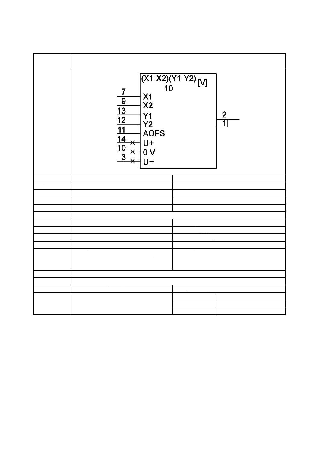
乗算器
Multiplier
別の名称
−
−
様式
−
−
別様式
13-07-02
S01780
注釈
A00352
適用分類
回路図
Circuit diagrams
機能分類
信号又は情報の処理(K)
K Processing signals or information
形状分類
文字,長方形
Characters, Rectangles
制限事項
−
−
補足事項
例えばAD532D
図記号13-07-02(S01780)は,他の機能を果
たす同一デバイスを表示したものである。
E.g. AD532D.
Symbol S01780 depicts the same device performing
another function.
適用図記号
S01753,S01761,S01764,S01778
被適用図記号
−
キーワード
アナログ回路,算術演算回路
analogue circuits, mathematical function circuits
注記
−
Status level
Standard
Released on
2004-09-13
Obsolete from
−
40
C 0617-13:2011
2019年7月1日の法改正により名称が変わりました。まえがきを除き,本規格中の「日本工業規格」を「日本産業規格」に読み替えてください。
第7節 算術演算機能を果たす素子の例
図記号番号
(識別番号)
図記号(Symbol)
13-07-02
(S01780)
項目
説明
IEC 60617情報(参考)
名称
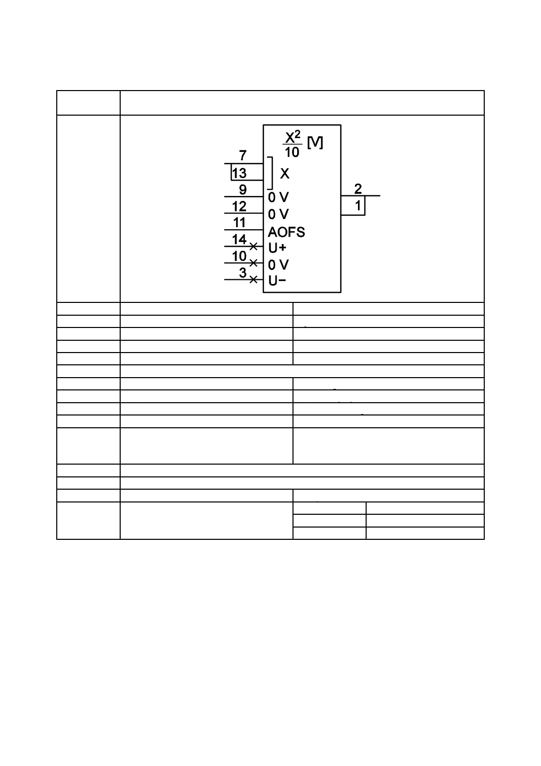
平方器
Squarer
別の名称
−
−
様式
−
−
別様式
13-07-01
S01779
注釈
A00352
適用分類
回路図
Circuit diagrams
機能分類
信号又は情報の処理(K)
K Processing signals or information
形状分類
文字,長方形
Characters, Rectangles
制限事項
−
−
補足事項
例えばAD532D
図記号13-07-01(S01779)は,他の機能を果
たす同一のデバイスを表示したものである。
E.g. AD532D.
Symbol S01779 depicts the same device performing
another function.
適用図記号
S01753,S01761,S01764,S01778
被適用図記号
−
キーワード
アナログ回路,算術演算回路
analogue circuits, mathematical function circuits
注記
−
Status level
Standard
Released on
2004-09-13
Obsolete from
−
41
C 0617-13:2011
2019年7月1日の法改正により名称が変わりました。まえがきを除き,本規格中の「日本工業規格」を「日本産業規格」に読み替えてください。
第8節 増幅器
図記号番号
(識別番号)
図記号(Symbol)
13-08-01
(S01781)
項目
説明
IEC 60617情報(参考)
名称
増幅器(一般図記号)
Amplifier, general symbol
別の名称
−
−
様式
様式3
form 3
別様式
10-15-01,10-15-02
S01239,S01240
注釈
A00325,A00352
適用分類
回路図,機能図,概要図
Circuit diagrams, Function diagrams, Overview
diagrams
機能分類
信号又は情報の処理(K)
K Processing signals or information
形状分類
文字,長方形
Characters, Rectangles
制限事項
−
−
42
C 0617-13:2011
2019年7月1日の法改正により名称が変わりました。まえがきを除き,本規格中の「日本工業規格」を「日本産業規格」に読み替えてください。
補足事項
ui = m·mi·f (w1·a1, w2·a2, ..., wn·an) where i = 1,
2, ..., k
素子が,増幅以外の特定の機能を果たす場
合,“f ”を適切な限定図記号で置き換えても
よい。その他の場合は“f ”を省略しなけれ
ばならない。次の機能に対しては,次の限定
図記号を用いなければならない。
− 加算
− 積分
d/dt−時間微分
exp−指数関数
log−対数(底10)
SH−サンプルホールド
m·miは,出力iの増幅率と等しい。
mは,増幅率の共通因数を表す。
共通因数が(可変ではなく)固定であって,
それを表示する必要がある場合,“m”を数字,
又は共通因子の絶対値若しくはその固定値
の範囲を表す表示によって置き換えなけれ
ばならない。
共通因数が可変であって,それを表示する必
要がある場合,“m”を表示して,“m”の値を
決定する方法を図記号の内部又は支援文書
のいずれかに示さなければならない。その他
の場合,“m”を省略しなければならない。
次の表示は,固定の共通因子を示すのに使用
するのが望ましい。
− 共通因子が大きいとき
1−共通因子が1であるとき
数字−共通因子を明示する必要があると
き
*1 ... *2−共通因子が*1 ... *2の範囲で固
定であるとき
*1及び*2は,それぞれを最小因子及び最
大因子で置き換えなければならない。
m1 ... mkは,増幅率の出力因子の符号付き値
を表す。出力因子の大きさが1と等しいとき,
“1”を省略してもよい。
ui = m·mi·f (w1·a1, w2·a2, ... ,wn·an) where i = 1,
2, ... ,k
If an element performs a specific function in addition
to amplification, "f" may be replaced by an appropriate
qualifying symbol. Otherwise "f " shall be omitted. The
following qualifying symbols should be used for the
functions listed:
− summing;
− integration;
d/dt−differentiating with respect to time;
exp−exponentiation;
log−logarithmic (base 10);
SH−sample-and-hold.
m·mi equals the amplification for output i.
m represents the common factor of the amplification.
If the common factor is fixed and is to be shown, the
"m" shall be replaced by a number or expression giving
the absolute value of the common factor or the range
within which it is fixed.
If the common factor is variable and that fact is to be
shown, "m" shall be shown and the way to determine
the value of m shall be shown either inside the symbol
or in supporting documentation. Otherwise the "m"
shall be omitted.
The following indications should be used for
indicating a fixed common factor:
− if the common factor is large;
1−if the common factor is 1;
a number−if the common factor is to be shown
explicitly;
*1 ... *2−if the common factor is fixed within the
range *1 ... *2.
*1 and *2 shall be replaced by the smallest and by
the largest factors in the range, respectively.
m1 ... mk represe
適用図記号
S01457,S01463
被適用図記号
S01782,S01784,S01783,S01787,S01786,S01790,S01789,S01785,S01788
キーワード
増幅器,アナログ素子
amplifiers, analogue elements
注記
−
Status level
Standard
Released on
2004-09-13
Obsolete from
−
43
C 0617-13:2011
2019年7月1日の法改正により名称が変わりました。まえがきを除き,本規格中の「日本工業規格」を「日本産業規格」に読み替えてください。
第9節 増幅器の例
図記号番号
(識別番号)
図記号(Symbol)
13-09-01
(S01782)
項目
説明
IEC 60617情報(参考)
名称
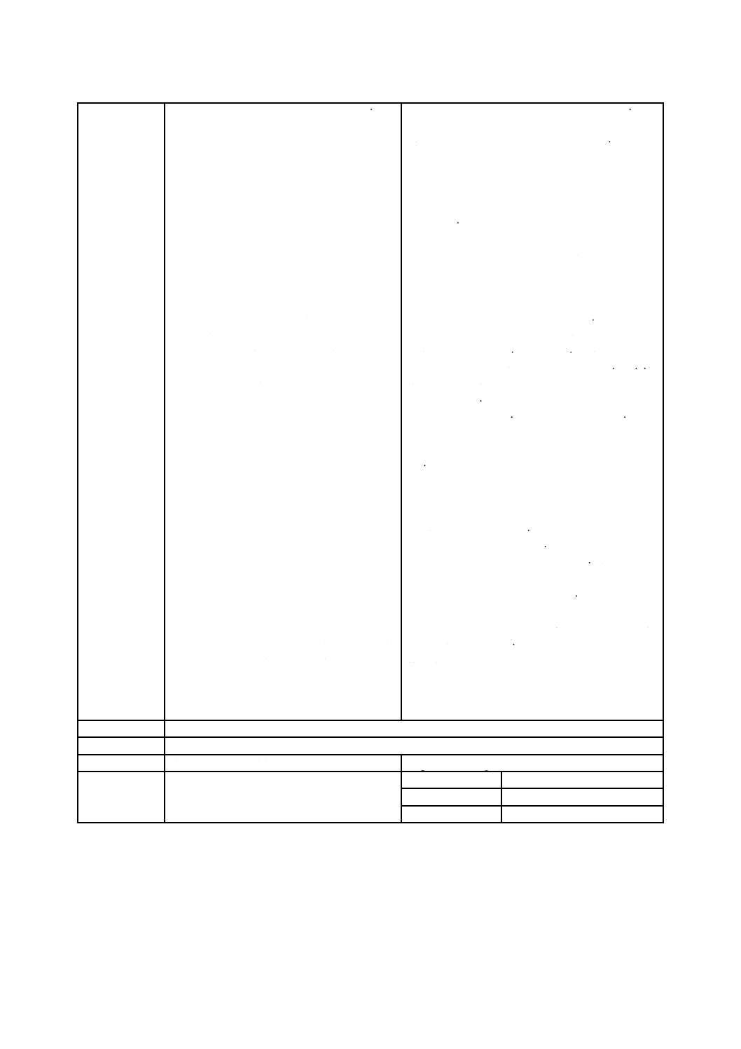
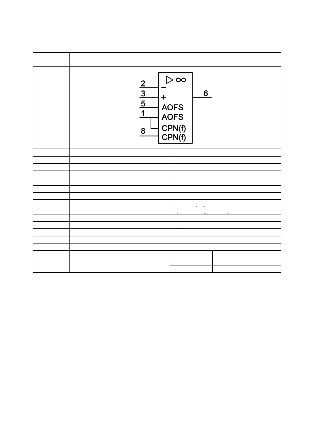
演算増幅器
Operational amplifier
別の名称
オペアンプ
−
様式
−
−
別様式
−
−
注釈
A00352
適用分類
回路図,機能図
Circuit diagrams, Function diagrams
機能分類
信号又は情報の処理(K)
K Processing signals or information
形状分類
正三角形,長方形
Equilateral triangles, Rectangles
制限事項
−
−
補足事項
例えばLM324
E.g. part of LM324.
適用図記号
S01781
被適用図記号
S01740
キーワード
増幅器,アナログ回路
amplifiers, analogue circuits
注記
−
Status level
Standard
Released on
2004-09-13
Obsolete from
−
44
C 0617-13:2011
2019年7月1日の法改正により名称が変わりました。まえがきを除き,本規格中の「日本工業規格」を「日本産業規格」に読み替えてください。
第9節 増幅器の例
図記号番号
(識別番号)
図記号(Symbol)
13-09-02
(S01783)
項目
説明
IEC 60617情報(参考)
名称
演算増幅器
Operational amplifier
別の名称
オペアンプ
−
様式
−
−
別様式
−
−
注釈
−
適用分類
回路図,機能図
Circuit diagrams, Function diagrams
機能分類
信号又は情報の処理(K)
K Processing signals or information
形状分類
正三角形,長方形
Equilateral triangles, Rectangles
制限事項
−
−
補足事項
例えばLM741
E.g. LM741.
適用図記号
S01764,S01781
被適用図記号
−
キーワード
増幅器,アナログ回路
amplifiers, analogue circuits
注記
−
Status level
Standard
Released on
2004-09-13
Obsolete from
−
45
C 0617-13:2011
2019年7月1日の法改正により名称が変わりました。まえがきを除き,本規格中の「日本工業規格」を「日本産業規格」に読み替えてください。
第9節 増幅器の例
図記号番号
(識別番号)
図記号(Symbol)
13-09-03
(S01784)
項目
説明
IEC 60617情報(参考)
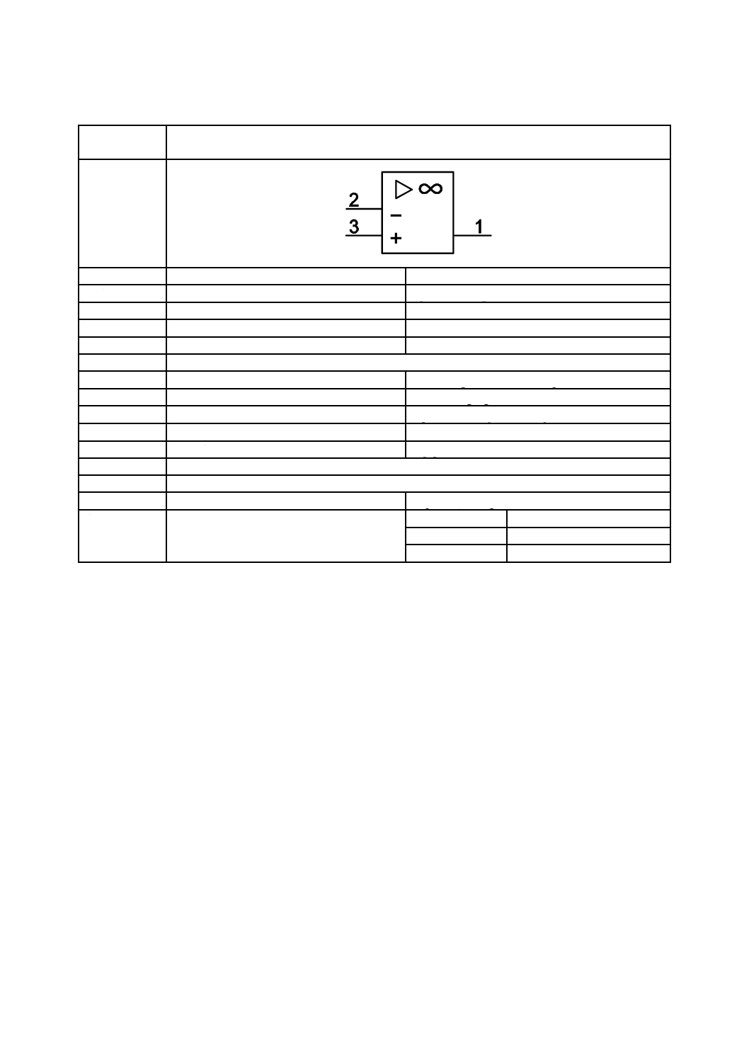
名称
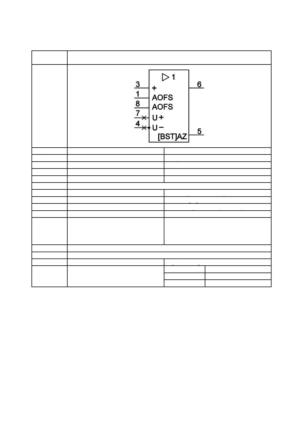
演算増幅器
Operational amplifier
別の名称
オペアンプ
−
様式
−
−
別様式
−
−
注釈
−
適用分類
回路図,機能図
Circuit diagrams, Function diagrams
機能分類
信号又は情報の処理(K)
K Processing signals or information
形状分類
正三角形,長方形
Equilateral triangles, Rectangles
制限事項
−
−
補足事項
例えばLM301A
E.g. LM301A.
適用図記号
S01764,S01765,S01781
被適用図記号
−
キーワード
増幅器,アナログ回路
amplifiers, analogue circuits
注記
−
Status level
Standard
Released on
2004-09-13
Obsolete from
−
46
C 0617-13:2011
2019年7月1日の法改正により名称が変わりました。まえがきを除き,本規格中の「日本工業規格」を「日本産業規格」に読み替えてください。
第9節 増幅器の例
図記号番号
(識別番号)
図記号(Symbol)
13-09-04
(S01785)
項目
説明
IEC 60617情報(参考)
名称
電圧フォロア
Voltage follower
別の名称
−
−
様式
−
−
別様式
−
−
注釈
A00352
適用分類
回路図,機能図
Circuit diagrams, Function diagrams
機能分類
信号又は情報の処理(K)
K Processing signals or information
形状分類
文字,正三角形,長方形
Characters, Equilateral triangles, Rectangles
制限事項
−
−
補足事項
例えばLM310メタルカンパッケージ
ここに使用している ,図記号03-02-01
(S00016)(黒丸)は,ケース(外囲器)を
端子に接続していることを表している。
E.g., LM310, metal-can package.
This use of symbol S00016 (the dot) represents the
connection of the case (envelope) to a terminal.
適用図記号
S00016,S01546,S01764,S01781
被適用図記号
−
キーワード
増幅器,アナログ回路
amplifiers, analogue circuits
注記
−
Status level
Standard
Released on
2004-09-13
Obsolete from
−
47
C 0617-13:2011
2019年7月1日の法改正により名称が変わりました。まえがきを除き,本規格中の「日本工業規格」を「日本産業規格」に読み替えてください。
第9節 増幅器の例
図記号番号
(識別番号)
図記号(Symbol)
13-09-05
(S01786)
項目
説明
IEC 60617情報(参考)
名称
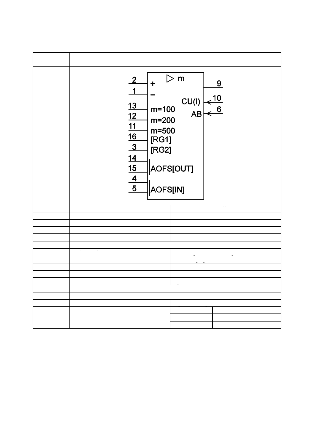
増幅器(増幅率選択式)
Amplifier with selectable amplification
別の名称
−
−
様式
−
−
別様式
−
−
注釈
A00352
適用分類
回路図,機能図
Circuit diagrams, Function diagrams
機能分類
信号又は情報の処理(K)
K Processing signals or information
形状分類
正三角形,長方形
Equilateral triangles, Rectangles
制限事項
−
−
補足事項
例えばAD624
E.g. AD624.
適用図記号
S01518,S01764,S01765,S01781
被適用図記号
−
キーワード
増幅器,アナログ回路
amplifiers, analogue circuits
注記
−
Status level
Standard
Released on
2004-09-13
Obsolete from
−
48
C 0617-13:2011
2019年7月1日の法改正により名称が変わりました。まえがきを除き,本規格中の「日本工業規格」を「日本産業規格」に読み替えてください。
第9節 増幅器の例
図記号番号
(識別番号)
図記号(Symbol)
13-09-06
(S01787)
項目
説明
IEC 60617情報(参考)
名称
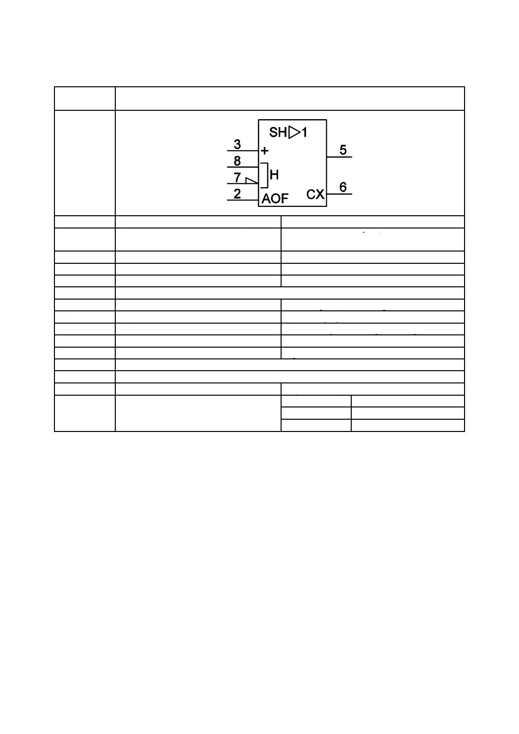
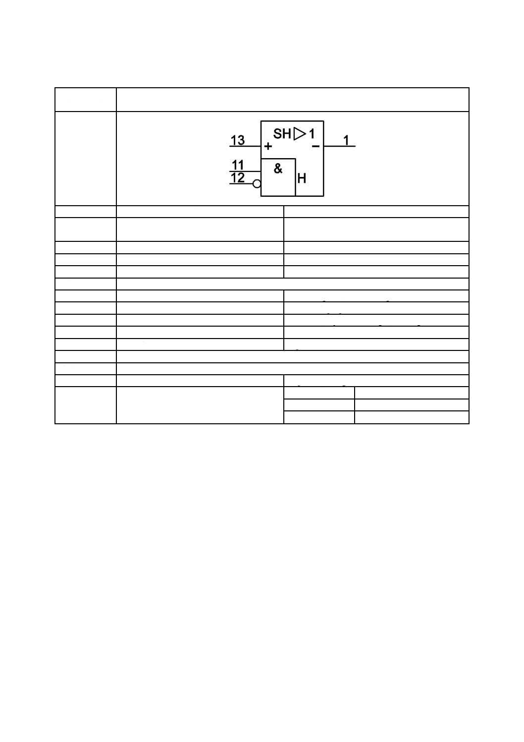
増幅器(サンプルホールド付き),(増幅率1) Sample-and-hold amplifier with an amplification factor
of one
別の名称
−
−
様式
−
−
別様式
−
−
注釈
A00352
適用分類
回路図,機能図
Circuit diagrams, Function diagrams
機能分類
信号又は情報の処理(K)
K Processing signals or information
形状分類
文字,正三角形,長方形
Characters, Equilateral triangles, Rectangles
制限事項
−
−
補足事項
例えばLF398
E.g. LF398.
適用図記号
S01468,S01540,S01764,S01765,S01768,S01781
被適用図記号
−
キーワード
増幅器,アナログ回路
amplifiers, analogue circuits
注記
−
Status level
Standard
Released on
2004-09-13
Obsolete from
−
49
C 0617-13:2011
2019年7月1日の法改正により名称が変わりました。まえがきを除き,本規格中の「日本工業規格」を「日本産業規格」に読み替えてください。
第9節 増幅器の例
図記号番号
(識別番号)
図記号(Symbol)
13-09-07
(S01788)
項目
説明
IEC 60617情報(参考)
名称
増幅器(入出力絶縁型)
Amplifier, isolating
別の名称
−
−
様式
−
−
別様式
−
−
注釈
A00352
適用分類
回路図,機能図
Circuit diagrams, Function diagrams
機能分類
信号又は情報の処理(K)
K Processing signals or information
形状分類
文字,正三角形,長方形
Characters, Equilateral triangles, Rectangles
制限事項
−
−
補足事項
例えばAD293
E.g. AD293.
適用図記号
S01407,S01518,S01764,S01781
被適用図記号
−
キーワード
増幅器,アナログ回路
amplifiers, analogue circuits
注記
−
Status level
Standard
Released on
2004-09-13
Obsolete from
−
50
C 0617-13:2011
2019年7月1日の法改正により名称が変わりました。まえがきを除き,本規格中の「日本工業規格」を「日本産業規格」に読み替えてください。
第9節 増幅器の例
図記号番号
(識別番号)
図記号(Symbol)
13-09-08
(S01789)
項目
説明
IEC 60617情報(参考)
名称
増幅器(サンプルホールド付き)(増幅率1) Sample-and-hold amplifier with an amplification factor
of one
別の名称
−
−
様式
−
−
別様式
−
−
注釈
A00352
適用分類
回路図,機能図
Circuit diagrams, Function diagrams
機能分類
信号又は情報の処理(K)
K Processing signals or information
形状分類
文字,正三角形,長方形
Characters, Equilateral triangles, Rectangles
制限事項
−
−
補足事項
例えば4860
E.g. 4860
適用図記号
S01466,S01476,S01567,S01768,S01781
被適用図記号
−
キーワード
増幅器,アナログ回路
amplifiers, analogue circuits
注記
−
Status level
Standard
Released on
2004-09-13
Obsolete from
−
51
C 0617-13:2011
2019年7月1日の法改正により名称が変わりました。まえがきを除き,本規格中の「日本工業規格」を「日本産業規格」に読み替えてください。
第9節 増幅器の例
図記号番号
(識別番号)
図記号(Symbol)
13-09-09
(S01790)
項目
説明
IEC 60617情報(参考)
名称
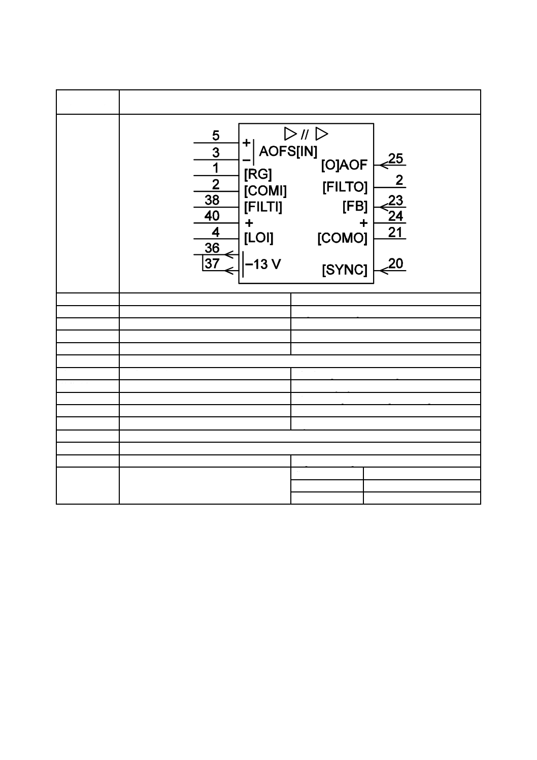
演算増幅器(マルチプレックス入力付き:4
入力から1入力を選択)
Operational amplifier with multiplexed inputs (one of
four)
別の名称
−
−
様式
−
−
別様式
−
−
注釈
A00352
適用分類
回路図,機能図
Circuit diagrams, Function diagrams
機能分類
信号又は情報の処理(K)
K Processing signals or information
形状分類
文字,正三角形,長方形
Characters, Equilateral triangles, Rectangles
制限事項
−
−
補足事項
例えばHA-2400
ここに用いている,図記号03-02-01(S00016)
(黒丸)は,ケース(外囲器)を端子に接続
していることを表している。
E.g. HA-2400.
This use of symbol S00016 (the dot) represents the
connection of the case (envelope) to a terminal.
適用図記号
S00016,S01750,S01753,S01765,S01773,S01781,S01810
被適用図記号
−
キーワード
増幅器,アナログ回路
amplifiers, analogue circuits
注記
−
Status level
Standard
52
C 0617-13:2011
2019年7月1日の法改正により名称が変わりました。まえがきを除き,本規格中の「日本工業規格」を「日本産業規格」に読み替えてください。
Released on
2004-09-13
Obsolete from
−
53
C 0617-13:2011
2019年7月1日の法改正により名称が変わりました。まえがきを除き,本規格中の「日本工業規格」を「日本産業規格」に読み替えてください。
第IV章 変換器
第10節 一般
図記号番号
(識別番号)
図記号(Symbol)
13-10-01
(S01791)
項目
説明
IEC 60617情報(参考)
名称
変換器(一般図記号)
Converter, general symbol
別の名称
−
−
様式
−
−
別様式
−
−
注釈
A00296,A00327,A00352
適用分類
回路図,機能図,概要図
Circuit diagrams, Function diagrams, Overview
diagrams
機能分類
信号又は情報の処理(K),
同種の変換(T)
K Processing signals or information,
T Converting but maintaining kind
形状分類
文字,長方形
Characters, Rectangles
制限事項
−
−
補足事項
絶縁を表示する必要がある場合には,一般限
定図記号* / *を* //*で置き換えてもよい。
アスタリスクは,関係する量又は特性の適切
な表示で置き換えなければならない。
左側のアスタリスクは入力を指し,右側のア
スタリスクは出力を指す。
次の項目に対して,次の表示を用いなければ
ならない。
#−符号を特定しないディジタル値
− 機能を特定しないアナログ値
U又はV−電圧
f−周波数
φ−位相
I−電流
T−温度
一般限定図記号#/及び/#は,DAC及びADC
で置き換えてもよい。
一般限定図記号#/及び/#において,#を,ディ
ジタル入力[出力]が内部値を決定[表示]
するために使用する符号の適切な表示で置
き換えてもよい。この場合,ディジタル入力
[出力]に,この符号を表す文字を付けなけ
ればならない。この方法についての詳細は,
注釈A00296の1.1を参照する。
The general qualifying symbol * / * may be replaced by
* //* if it is necessary to indicate electrical isolation.
The asterisks shall be replaced by appropriate
indications of the quantities or qualities con-cerned.
The left asterisk refers to the input; the right asterisk
refers to the output.
The following indications should be used for the items
listed:
#−digital, code unspecified;
− analogue, function unspecified;
U or V−voltage;
f−frequency;
φ−phase;
I−current;
T−temperature.
The general qualifying symbols #/ and /# may be
replaced by DAC and ADC rsp.
In the general qualifying symbols #/ and /#, # may be
replaced by an appropriate indication of the code used
at the digital inputs [outputs] to determine [represent]
the internal value, In this case, the digital inputs
[outputs] shall be labelled with characters that refer to
this code. See 1.1 of A00296 for further information on
this method.
適用図記号
S00214; S01407; S01463
被適用図記号
S01793,S01794,S01795,S01792
キーワード
アナログ素子,変換器
analogue elements, converters
54
C 0617-13:2011
2019年7月1日の法改正により名称が変わりました。まえがきを除き,本規格中の「日本工業規格」を「日本産業規格」に読み替えてください。
注記
−
Status level
Standard
Released on
2004-09-13
Obsolete from
−
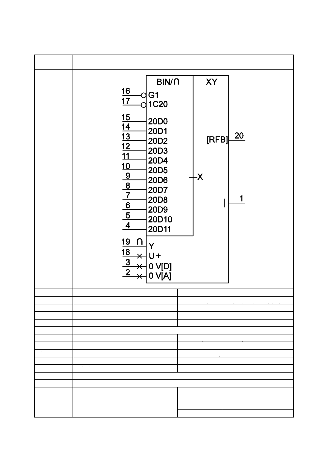
55
C 0617-13:2011
2019年7月1日の法改正により名称が変わりました。まえがきを除き,本規格中の「日本工業規格」を「日本産業規格」に読み替えてください。
第11節 変換器の例
図記号番号
(識別番号)
図記号(Symbol)
13-11-01
(S01792)
項目
説明
IEC 60617情報(参考)
名称
乗算形ディジタル−アナログ変換器(DAC) Converter, digital to analogue (DAC), multiplying
別の名称
−
−
様式
−
−
別様式
−
−
注釈
A00352
適用分類
回路図,機能図
Circuit diagrams, Function diagrams
機能分類
信号又は情報の処理(K)
K Processing signals or information
形状分類
文字,長方形
Characters, Rectangles
制限事項
−
−
補足事項
例えばAD7545
E.g. AD7545.
適用図記号
S01466,S01475,S01546,S01558,S01748,S01753,S01778,S01791,S01810
被適用図記号
−
キーワード
アナログ回路,演算回路,変換器,算術機能
回路
analogue circuits, arithmetic circuits, converters,
mathematical function circuits
注記
−
Status level
Standard
Released on
2004-09-13

56
C 0617-13:2011
2019年7月1日の法改正により名称が変わりました。まえがきを除き,本規格中の「日本工業規格」を「日本産業規格」に読み替えてください。
Obsolete from
−
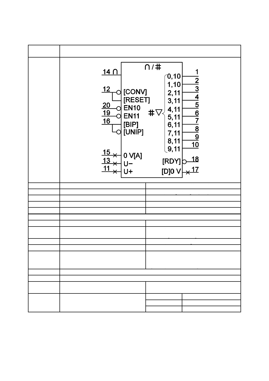
57
C 0617-13:2011
2019年7月1日の法改正により名称が変わりました。まえがきを除き,本規格中の「日本工業規格」を「日本産業規格」に読み替えてください。
第11節 変換器の例
図記号番号
(識別番号)
図記号(Symbol)
13-11-02
(S01793)
項目
説明
IEC 60617情報(参考)
名称
アナログ−ディジタル変換器(ADC)
Converter, analogue to digital (ADC)
別の名称
−
−
様式
−
−
別様式
−
−
注釈
A00352
適用分類
回路図,機能図
Circuit diagrams, Function diagrams
機能分類
信号又は情報の処理(K),
同種の変換(T)
K Processing signals or information,
T Converting but maintaining kind
形状分類
文字,線,長方形
Characters, Lines, Rectangles
制限事項
−
−
補足事項
例えばAD573
一般限定図記号#/及び/#は,DAC及びADC
で置き換えてもよい。
E.g. AD573.
The general qualifying symbols #/ and /# may be
replaced by DAC and ADC rsp.
適用図記号
S01466,S01467,S01498,S01562,S01748,S01753,S01791
被適用図記号
−
キーワード
アナログ回路,演算回路,変換器,算術機能
回路
analogue circuits, arithmetic circuits, converters,
mathematical function circuits
注記
−
Status level
Standard
Released on
2004-09-13
Obsolete from
−
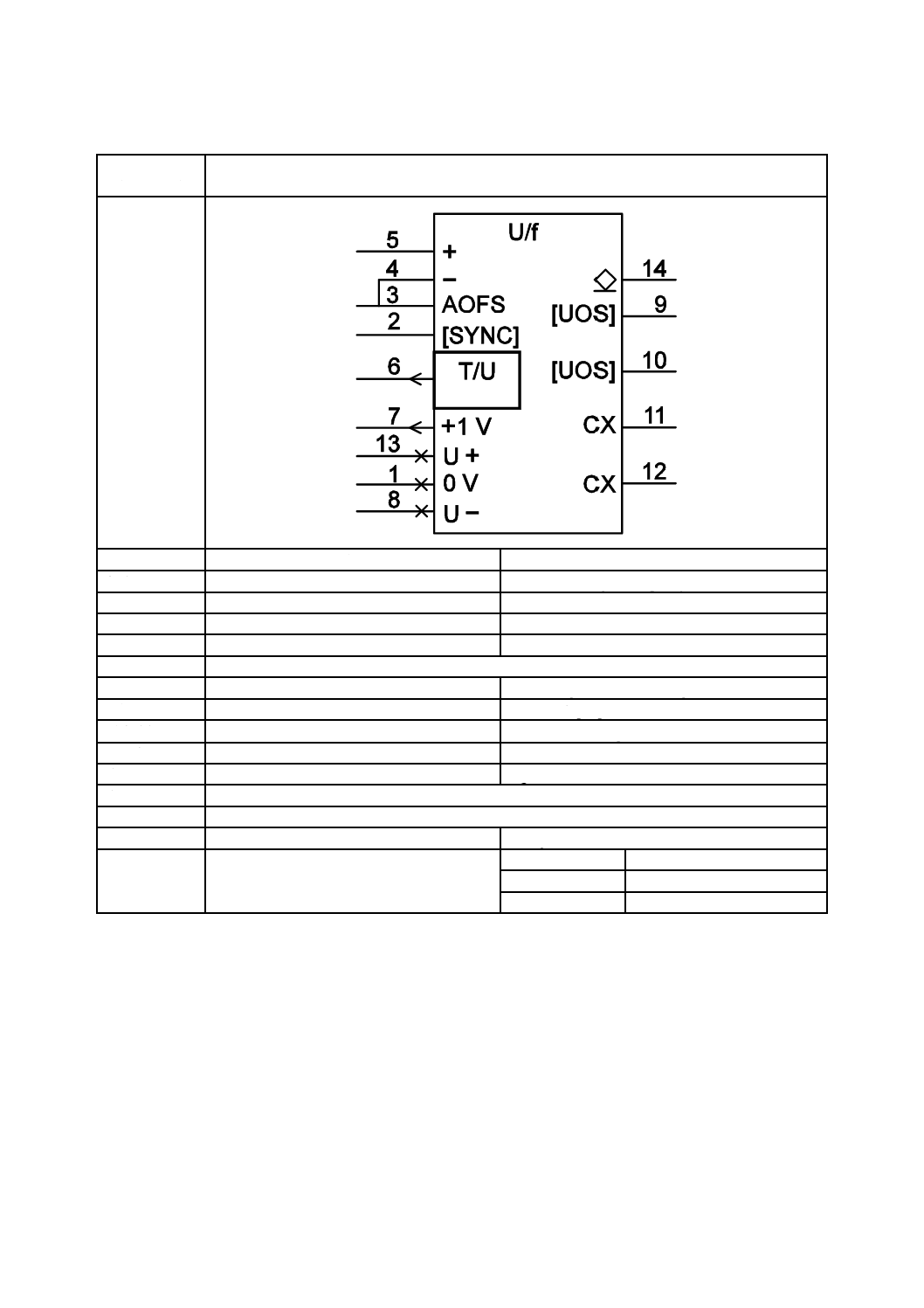
58
C 0617-13:2011
2019年7月1日の法改正により名称が変わりました。まえがきを除き,本規格中の「日本工業規格」を「日本産業規格」に読み替えてください。
第11節 変換器の例
図記号番号
(識別番号)
図記号(Symbol)
13-11-03
(S01794)
項目
説明
IEC 60617情報(参考)
名称
電圧−周波数変換器
Converter, voltage to frequency
別の名称
−
−
様式
−
−
別様式
−
−
注釈
A00352
適用分類
回路図,機能図
Circuit diagrams, Function diagrams
機能分類
信号又は情報の処理(K)
K Processing signals or information
形状分類
文字,長方形
Characters, Rectangles
制限事項
−
−
補足事項
例えばAD537
E.g. AD537.
適用図記号
S01495,S01753,S01764,S01765,S01791
被適用図記号
−
キーワード
アナログ回路,変換器
analogue circuits, converters
注記
−
Status level
Standard
Released on
2004-09-13
Obsolete from
−
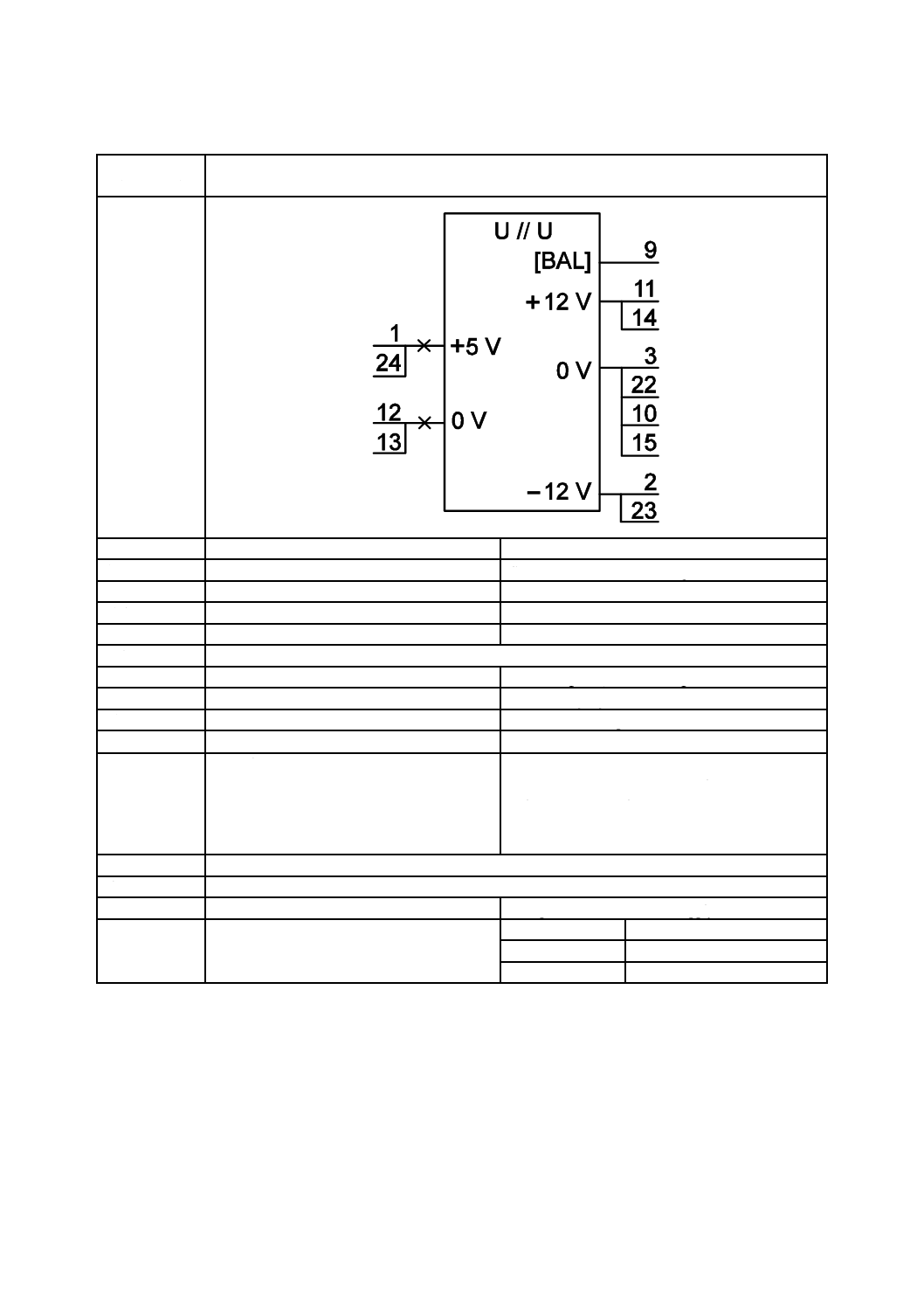
59
C 0617-13:2011
2019年7月1日の法改正により名称が変わりました。まえがきを除き,本規格中の「日本工業規格」を「日本産業規格」に読み替えてください。
第11節 変換器の例
図記号番号
(識別番号)
図記号(Symbol)
13-11-04
(S01795)
項目
説明
IEC 60617情報(参考)
名称
絶縁形直流−直流変換器
Converter, d.c.-to-d.c., isolating
別の名称
−
−
様式
−
−
別様式
−
−
注釈
A00328,A00352
適用分類
回路図,機能図
Circuit diagrams, Function diagrams
機能分類
信号又は情報の処理(K)
K Processing signals or information
形状分類
文字,長方形
Characters, Rectangles
制限事項
−
−
補足事項
例えばPM671P
端子2と23との間に,内部分岐を示してあ
る。このことを強調することが重要でなけれ
ば,ラベルグループ化図記号を用いてもよい
(図記号A00328を参照)。
E.g. PM671P.
Internal branches are shown, e.g., between terminals 2
and 23. If it is not important to emphasize this fact,
label-grouping symbols may be used, see A00328.
適用図記号
S01753,S01791
被適用図記号
−
キーワード
アナログ回路,変換器,電源回路
analogue circuits, converters, supply circuits
注記
−
Status level
Standard
Released on
2004-09-13
Obsolete from
−
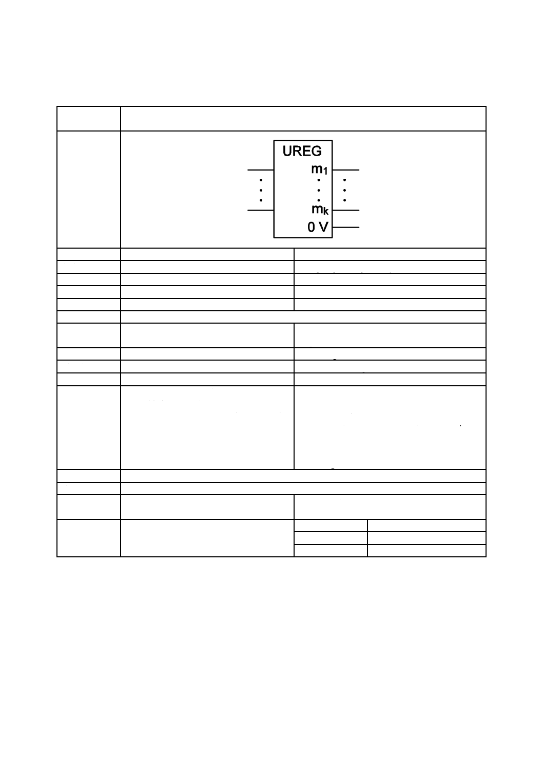
60
C 0617-13:2011
2019年7月1日の法改正により名称が変わりました。まえがきを除き,本規格中の「日本工業規格」を「日本産業規格」に読み替えてください。
第V章 調整器,比較器
第12節 電圧調整器
図記号番号
(識別番号)
図記号(Symbol)
13-12-01
(S01796)
項目
説明
IEC 60617情報(参考)
名称
電圧調整器(一般図記号)
Voltage regulator, general symbol
別の名称
−
−
様式
−
−
別様式
−
−
注釈
A00352
適用分類
回路図,機能図,概要図
Circuit diagrams, Function diagrams, Overview
diagrams
機能分類
流れの発生(G)
G Initiating a flow
形状分類
文字,長方形
Characters, Rectangles
制限事項
−
−
補足事項
m1 ... mk は,共通端子(0 V)に対して調整さ
れた(安定化された)電圧を表す。
m1 ... mk は,次のもので置き換えなければな
らない。
− U1 ... Uk,の各々の前に極性符号を付けた
もの。又は
− 調整された電圧の実際の値又は範囲。
m1 ... mk represent the regulated (stabilized) voltages
with respect to the common (0 V) terminal.
m1 ... mk shall be replaced by:
− U1 ... Uk, each followed by the polarity sign, or
by
− the actual values or ranges of the regulated
voltages.
適用図記号
S01463
被適用図記号
S01797,S01799,S01798
キーワード
アナログ素子,調整器,安定器,電源回路
analogue elements, regulators, stabilizers, supply
circuits
注記
−
Status level
Standard
Released on
2004-09-13
Obsolete from
−
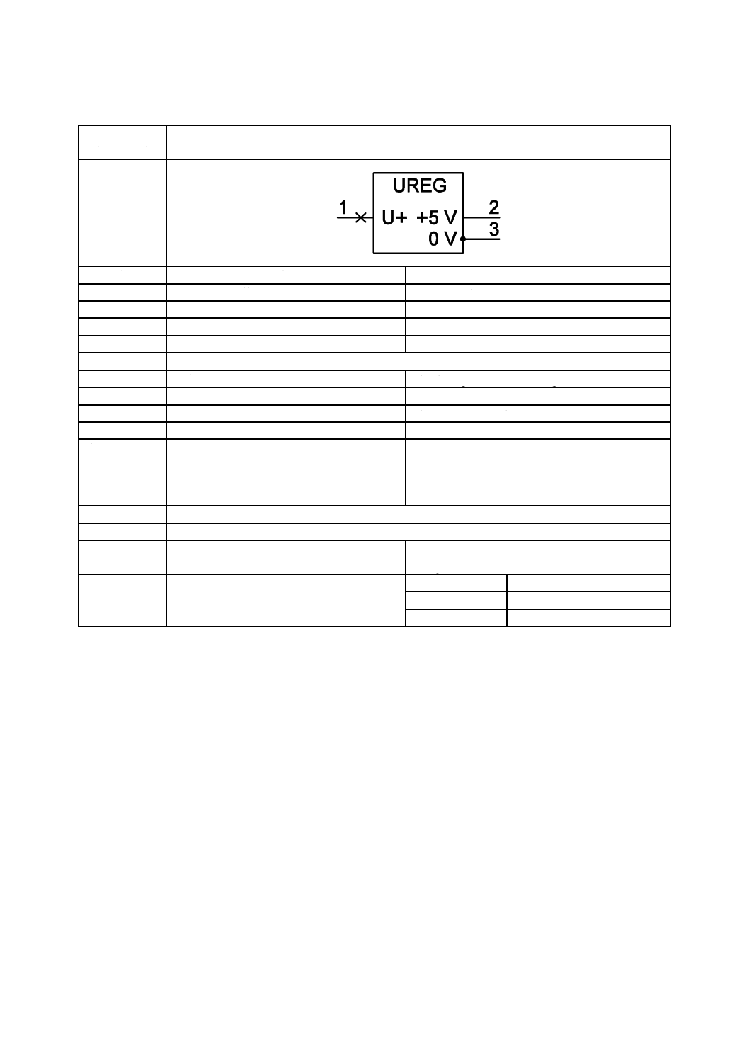
61
C 0617-13:2011
2019年7月1日の法改正により名称が変わりました。まえがきを除き,本規格中の「日本工業規格」を「日本産業規格」に読み替えてください。
第13節 電圧調整器の例
図記号番号
(識別番号)
図記号(Symbol)
13-13-01
(S01797)
項目
説明
IEC 60617情報(参考)
名称
固定正電圧調整器
Voltage regulator, positive, fixed
別の名称
−
−
様式
−
−
別様式
−
−
注釈
A00352
適用分類
回路図,機能図
Circuit diagrams, Function diagrams
機能分類
流れの発生(G)
G Initiating a flow
形状分類
文字,長方形
Characters, Rectangles
制限事項
−
−
補足事項
例えばLM309H
ここに用いている,図記号03-02-01(S00016)
(黒丸)は,ケース(外囲器)を端子に接続
していることを表している。
E.g. LM309H.
This use of symbol S00016 (the dot) represents the
connection of the case (envelope) to a terminal.
適用図記号
S00016,S01796
被適用図記号
−
キーワード
アナログ回路,電源回路,電圧調整器,電圧
安定器
analogue circuits, supply circuits, voltage regulators,
voltage stabilizers
注記
−
Status level
Standard
Released on
2004-09-13
Obsolete from
−
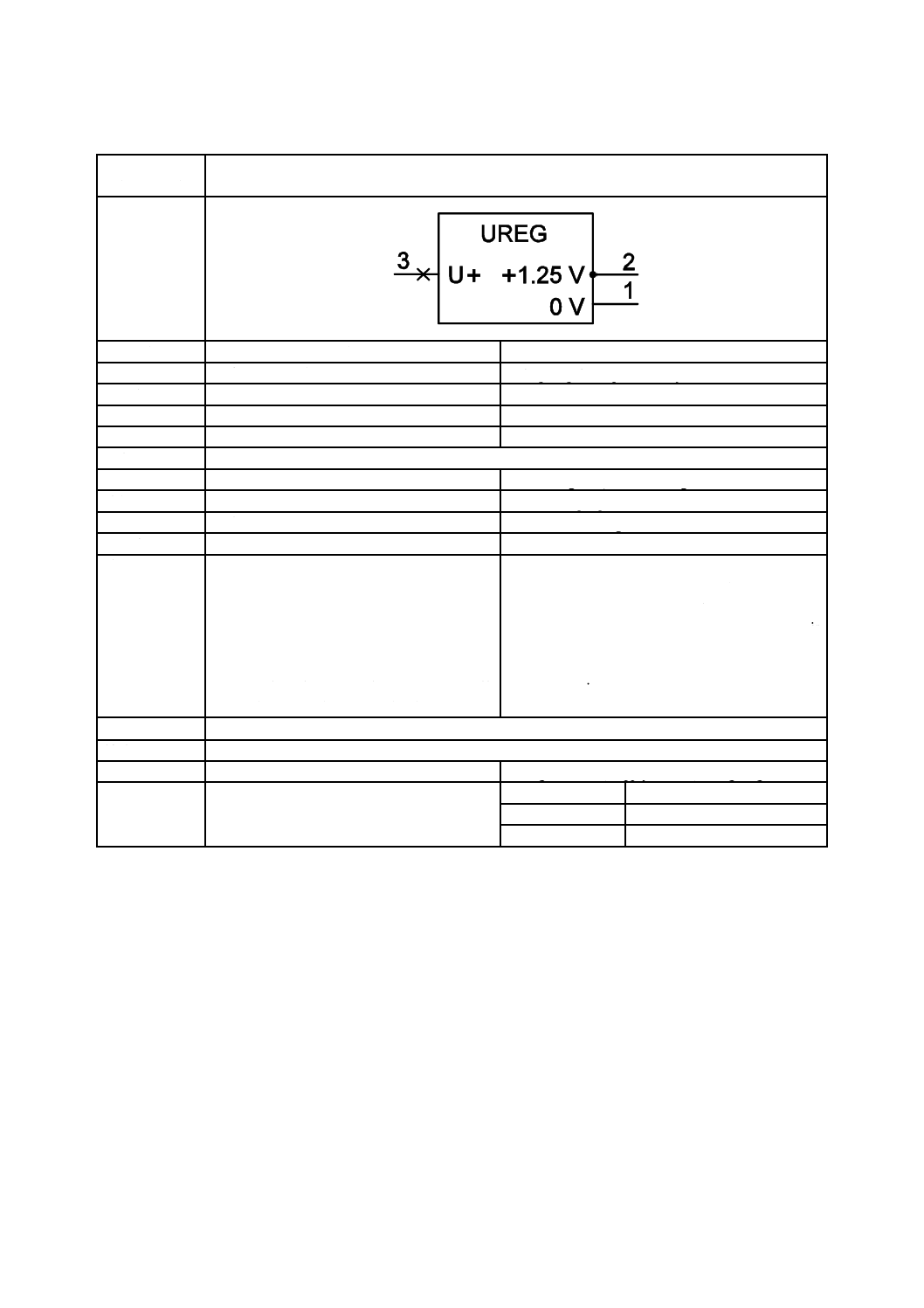
62
C 0617-13:2011
2019年7月1日の法改正により名称が変わりました。まえがきを除き,本規格中の「日本工業規格」を「日本産業規格」に読み替えてください。
第13節 電圧調整器の例
図記号番号
(識別番号)
図記号(Symbol)
13-13-02
(S01798)
項目
説明
IEC 60617情報(参考)
名称
可変正電圧調整器
Voltage regulator, positive, adjustable
別の名称
−
−
様式
−
−
別様式
−
−
注釈
A00330,A00352
適用分類
回路図,機能図
Circuit diagrams, Function diagrams
機能分類
信号又は情報の処理(K)
K Processing signals or information
形状分類
文字,長方形
Characters, Rectangles
制限事項
−
−
補足事項
例えばLM317T
ここに用いている,図記号03-02-01(S00016)
(黒丸)は,ケース(外囲器)を端子に接続
していることを表している。
端子1と2との間の電圧は固定されている
が,外部回路網を使用することによって,端
子2と外部回路網の他の点の間で種々の調整
電圧が得られる(A00330を参照)。
E.g. LM317T.
This use of symbol S00016 (the dot) represents the
connection of the case (envelope) to a terminal.
Although the voltage between terminals 2 and 1 is
fixed, an external network can be used to obtain a
different regulated voltage between terminal 2 and
another point in the network, see A00330.
適用図記号
S00016,S01546,S01796
被適用図記号
−
キーワード
アナログ回路,電源回路,電圧調整器
analogue circuits, supply circuits, voltage regulators
注記
−
Status level
Standard
Released on
2004-09-13
Obsolete from
−
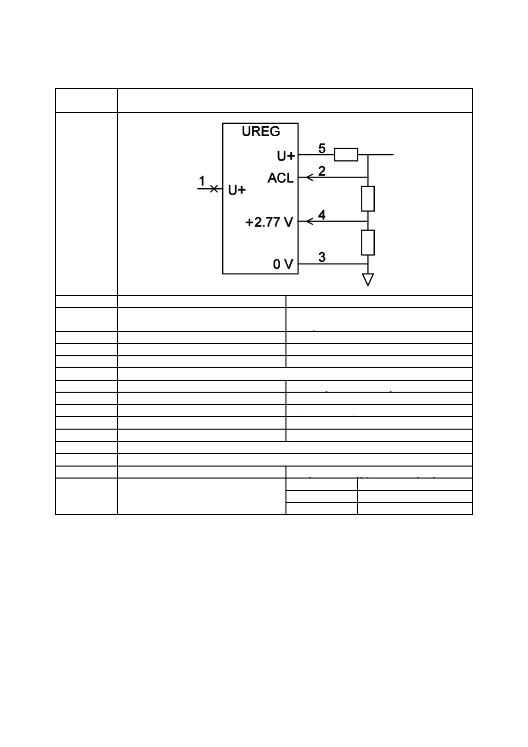
63
C 0617-13:2011
2019年7月1日の法改正により名称が変わりました。まえがきを除き,本規格中の「日本工業規格」を「日本産業規格」に読み替えてください。
第13節 電圧調整器の例
図記号番号
(識別番号)
図記号(Symbol)
13-13-03
(S01799)
項目
説明
IEC 60617情報(参考)
名称
可変正電圧調整器(電流制限付き)
Voltage regulator, positive, adjustable, with current
limiting
別の名称
−
−
様式
−
−
別様式
−
−
注釈
A00352
適用分類
回路図,機能図
Circuit diagrams, Function diagrams
機能分類
信号又は情報の処理(K)
K Processing signals or information
形状分類
文字,長方形
Characters, Rectangles
制限事項
−
−
補足事項
例えばL200CV
E.g. L200CV.
適用図記号
S00204,S00555,S01546,S01764,S01796
被適用図記号
−
キーワード
アナログ回路,電源回路,電圧調整器
analogue circuits, supply circuits, voltage regulators
注記
−
Status level
Standard
Released on
2004-09-13
Obsolete from
−
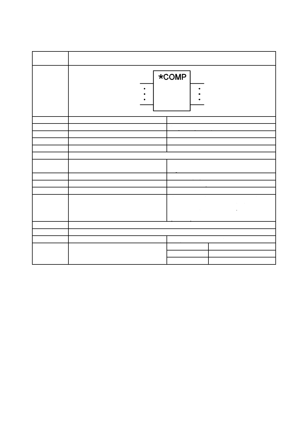
64
C 0617-13:2011
2019年7月1日の法改正により名称が変わりました。まえがきを除き,本規格中の「日本工業規格」を「日本産業規格」に読み替えてください。
第14節 比較器
図記号番号
(識別番号)
図記号(Symbol)
13-14-01
(S01800)
項目
説明
IEC 60617情報(参考)
名称
比較器(一般図記号)
Comparator, general symbol
別の名称
−
−
様式
−
−
別様式
−
−
注釈
A00352
適用分類
回路図,機能図,概要図
Circuit diagrams, Function diagrams, Overview
diagrams
機能分類
信号又は情報の処理(K)
K Processing signals or information
形状分類
文字,長方形
Characters, Rectangles
制限事項
−
−
補足事項
アスタリスクは,比較対象の適切な量又はオ
ペランドを示す文字記号で置き換えなけれ
ばならない。混乱を生じるおそれがなければ
文字記号を省略してもよい。
The asterisk shall be replaced by the appropriate letter
symbol for the quantity or operands whose values are
to be compared. If no confusion is likely, this letter
symbol may be omitted.
適用図記号
S01463
被適用図記号
S01715,S01713,S01802,S01801,S01806
キーワード
アナログ素子,比較器
analogue elements, comparators
注記
−
Status level
Standard
Released on
2004-09-13
Obsolete from
−
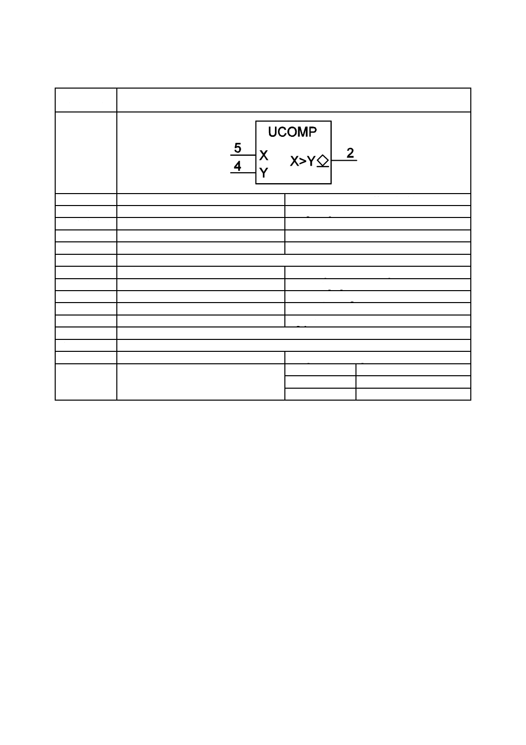
65
C 0617-13:2011
2019年7月1日の法改正により名称が変わりました。まえがきを除き,本規格中の「日本工業規格」を「日本産業規格」に読み替えてください。
第15節 比較器の例
図記号番号
(識別番号)
図記号(Symbol)
13-15-01
(S01801)
項目
説明
IEC 60617情報(参考)
名称
電圧比較器
Voltage comparator
別の名称
−
−
様式
−
−
別様式
−
−
注釈
A00352
適用分類
回路図,機能図
Circuit diagrams, Function diagrams
機能分類
信号又は情報の処理(K)
K Processing signals or information
形状分類
文字,長方形
Characters, Rectangles
制限事項
−
−
補足事項
例えばLM339
E.g. part of LM339.
適用図記号
S01495,S01770,S01800
被適用図記号
S01713,S01742
キーワード
アナログ回路,比較器
analogue circuits, comparators
注記
−
Status level
Standard
Released on
2004-09-13
Obsolete from
−
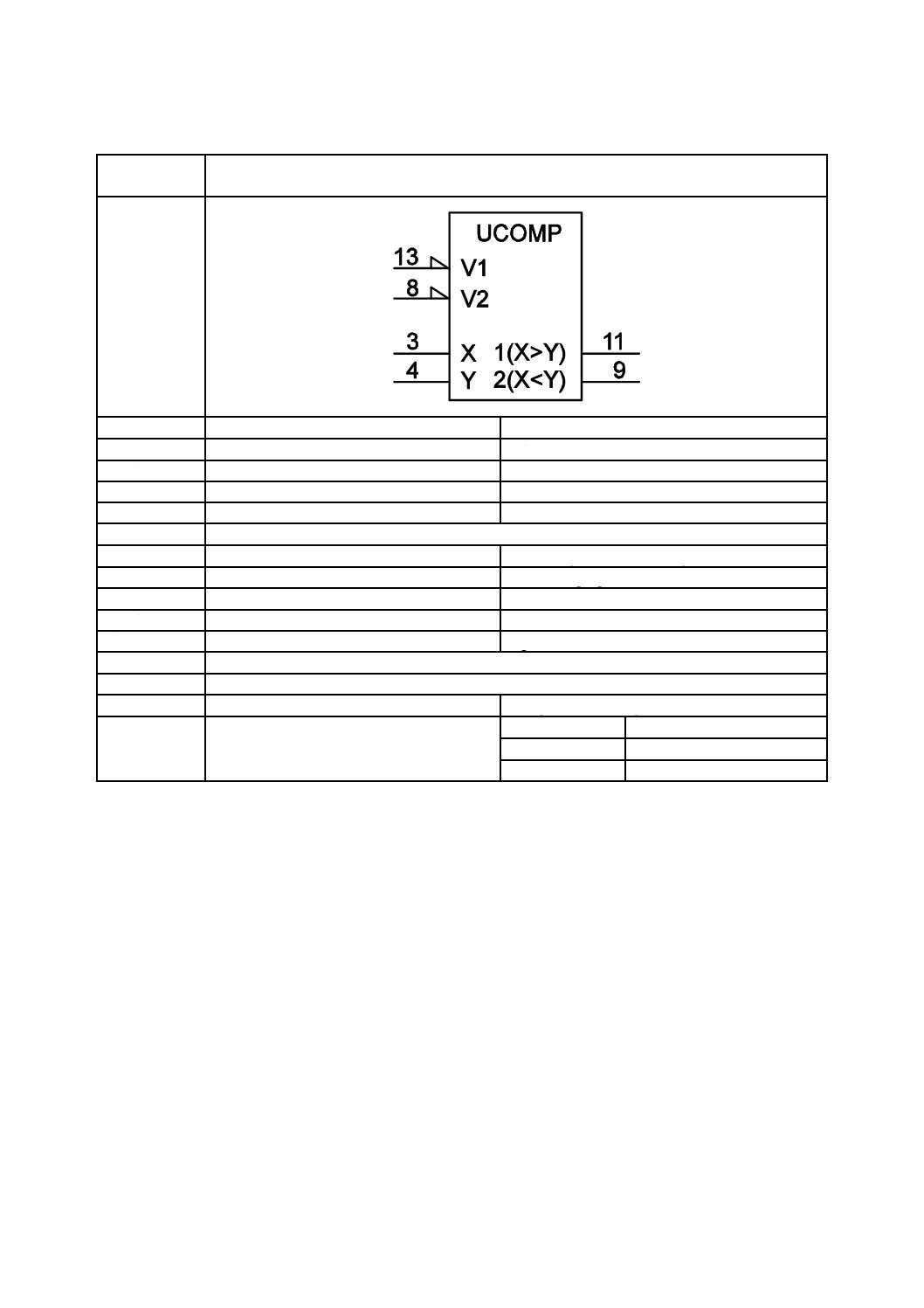
66
C 0617-13:2011
2019年7月1日の法改正により名称が変わりました。まえがきを除き,本規格中の「日本工業規格」を「日本産業規格」に読み替えてください。
第15節 比較器の例
図記号番号
(識別番号)
図記号(Symbol)
13-15-02
(S01802)
項目
説明
IEC 60617情報(参考)
名称
電圧比較器
Voltage comparator
別の名称
−
−
様式
−
−
別様式
−
−
注釈
A00352
適用分類
回路図,機能図
Circuit diagrams, Function diagrams
機能分類
信号又は情報の処理(K)
K Processing signals or information
形状分類
文字,長方形
Characters, Rectangles
制限事項
−
−
補足事項
例えばLM361
E.g. LM361.
適用図記号
S01468,S01550,S01770,S01800
被適用図記号
−
キーワード
アナログ回路,比較器
analogue circuits, comparators
注記
−
Status level
Standard
Released on
2004-09-13
Obsolete from
−
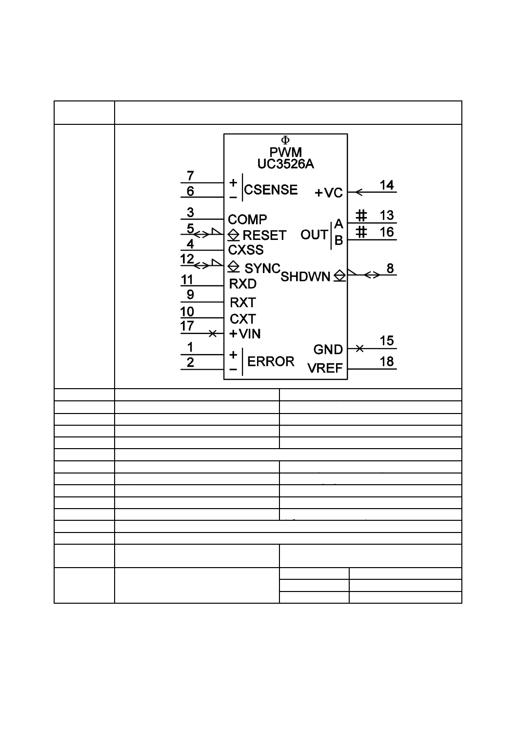
67
C 0617-13:2011
2019年7月1日の法改正により名称が変わりました。まえがきを除き,本規格中の「日本工業規格」を「日本産業規格」に読み替えてください。
第VI章 その他
第16節 複合機能素子の例
図記号番号
(識別番号)
図記号(Symbol)
13-16-01
(S01803)
項目
説明
IEC 60617情報(参考)
名称
パルス幅変調器
Pulse-width modulator
別の名称
−
−
様式
−
−
別様式
−
−
注釈
A00352
適用分類
回路図,機能図
Circuit diagrams, Function diagrams
機能分類
信号又は情報の処理(K)
K Processing signals or information
形状分類
文字,長方形
Characters, Rectangles
制限事項
−
−
補足事項
(例えばUC3526 A)
(e.g., Unitrode UC3526 A)
適用図記号
S00100,S01468,S01497,S01518,S01561,S01731,S01749,S01753,S01765
被適用図記号
−
キーワード
アナログ回路,複合機能回路,変調器
analogue
circuits,
complex
function
circuits,
modulators
注記
−
Status level
Standard
Released on
2004-09-13
Obsolete from
−
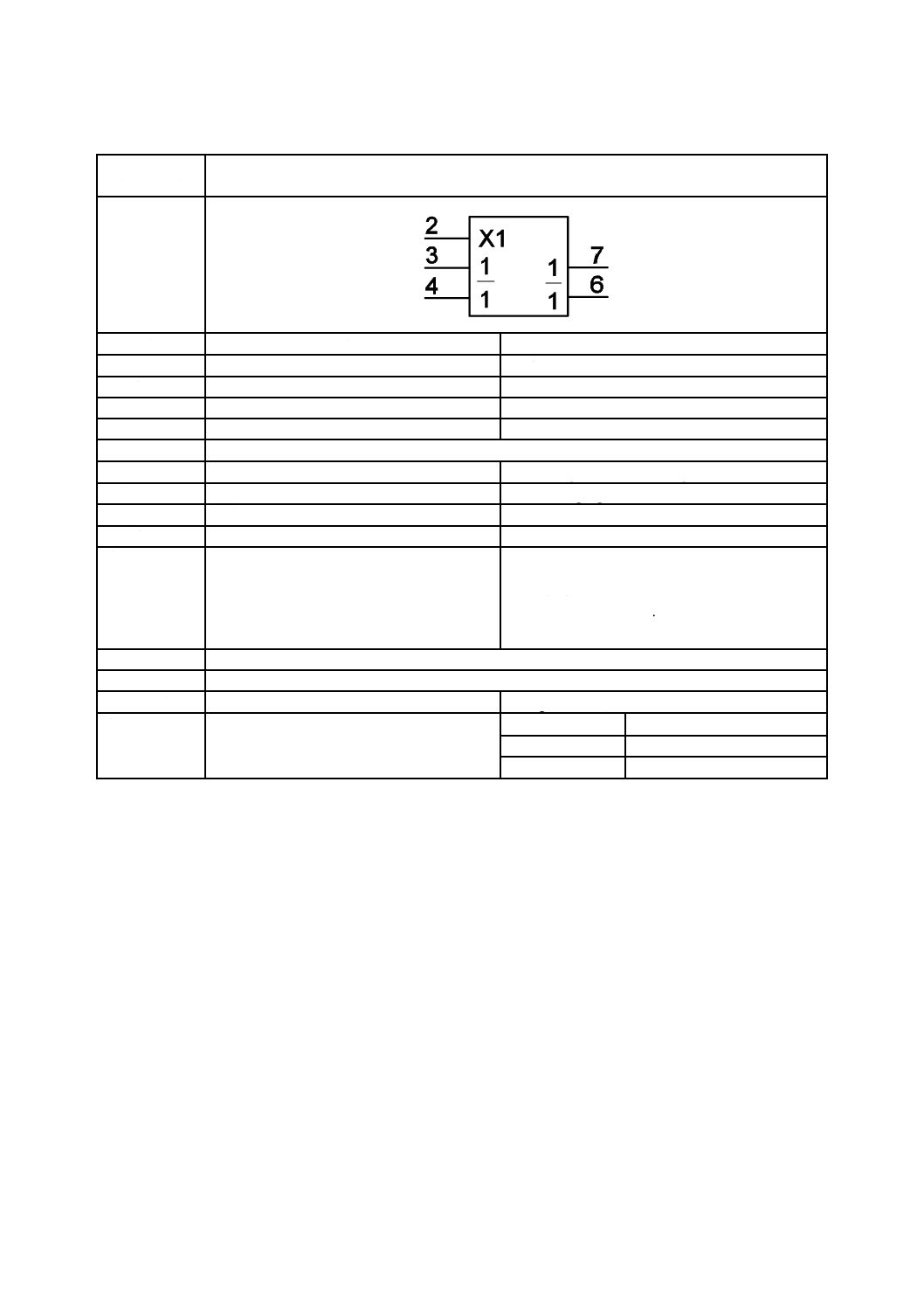
68
C 0617-13:2011
2019年7月1日の法改正により名称が変わりました。まえがきを除き,本規格中の「日本工業規格」を「日本産業規格」に読み替えてください。
第17節 電子スイッチの例
図記号番号
(識別番号)
図記号(Symbol)
13-17-01
(S01804)
項目
説明
IEC 60617情報(参考)
名称
アナログスイッチ
Analogue switch
別の名称
−
−
様式
−
−
別様式
−
−
注釈
A00281,A00352
適用分類
回路図,機能図
Circuit diagrams, Function diagrams
機能分類
信号又は情報の処理(K)
K Processing signals or information
形状分類
文字,長方形
Characters, Rectangles
制限事項
−
−
補足事項
例えばTL604
電子スイッチでは,入力と出力との接続を,
A00281に示すトランスミッション
(TRANSMISSION)依存関係で示さなければ
ならない。
E.g. TL604.
In electronic switches, the connections between inputs
and outputs shall be shown by TRANSMISSION (Xm)
dependancy as described in A00281.
適用図記号
S01776
被適用図記号
−
キーワード
アナログ回路,スイッチ
analogue circuits, switches
注記
−
Status level
Standard
Released on
2004-09-13
Obsolete from
−
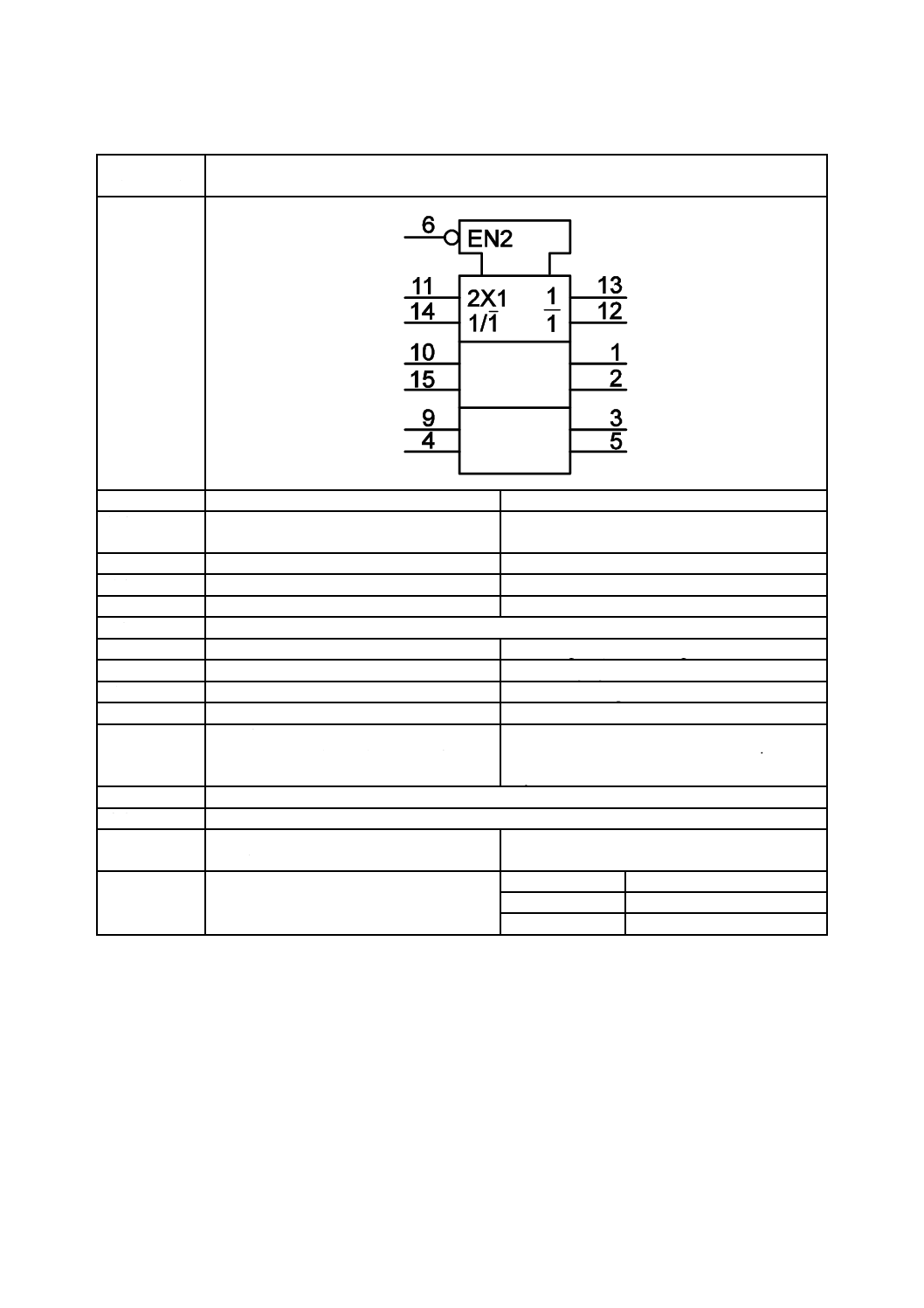
69
C 0617-13:2011
2019年7月1日の法改正により名称が変わりました。まえがきを除き,本規格中の「日本工業規格」を「日本産業規格」に読み替えてください。
第17節 電子スイッチの例
図記号番号
(識別番号)
図記号(Symbol)
13-17-02
(S01805)
項目
説明
IEC 60617情報(参考)
名称
アナログマルチプレクサ/デマルチプレク
サ(三組)
Analogue multiplexer/demultiplexer, triple
別の名称
−
−
様式
−
−
別様式
12-29-11
S01606
注釈
A00281,A00352
適用分類
回路図,機能図
Circuit diagrams, Function diagrams
機能分類
信号又は情報の処理(K)
K Processing signals or information
形状分類
文字,長方形
Characters, Rectangles
制限事項
−
−
補足事項
例えば74HC4053
図記号12-29-11(S01606)は,他の方法で同
一デバイスを説明している。
E.g. 74HC4053.
Symbol S01606 depicts the same device in another
way.
適用図記号
S01466,S01556,S01562
被適用図記号
−
キーワード
アナログ回路,デマルチプレクサ,マルチプ
レクサ
analogue circuits, demultiplexers, multiplexers
注記
−
Status level
Standard
Released on
2004-09-13
Obsolete from
−
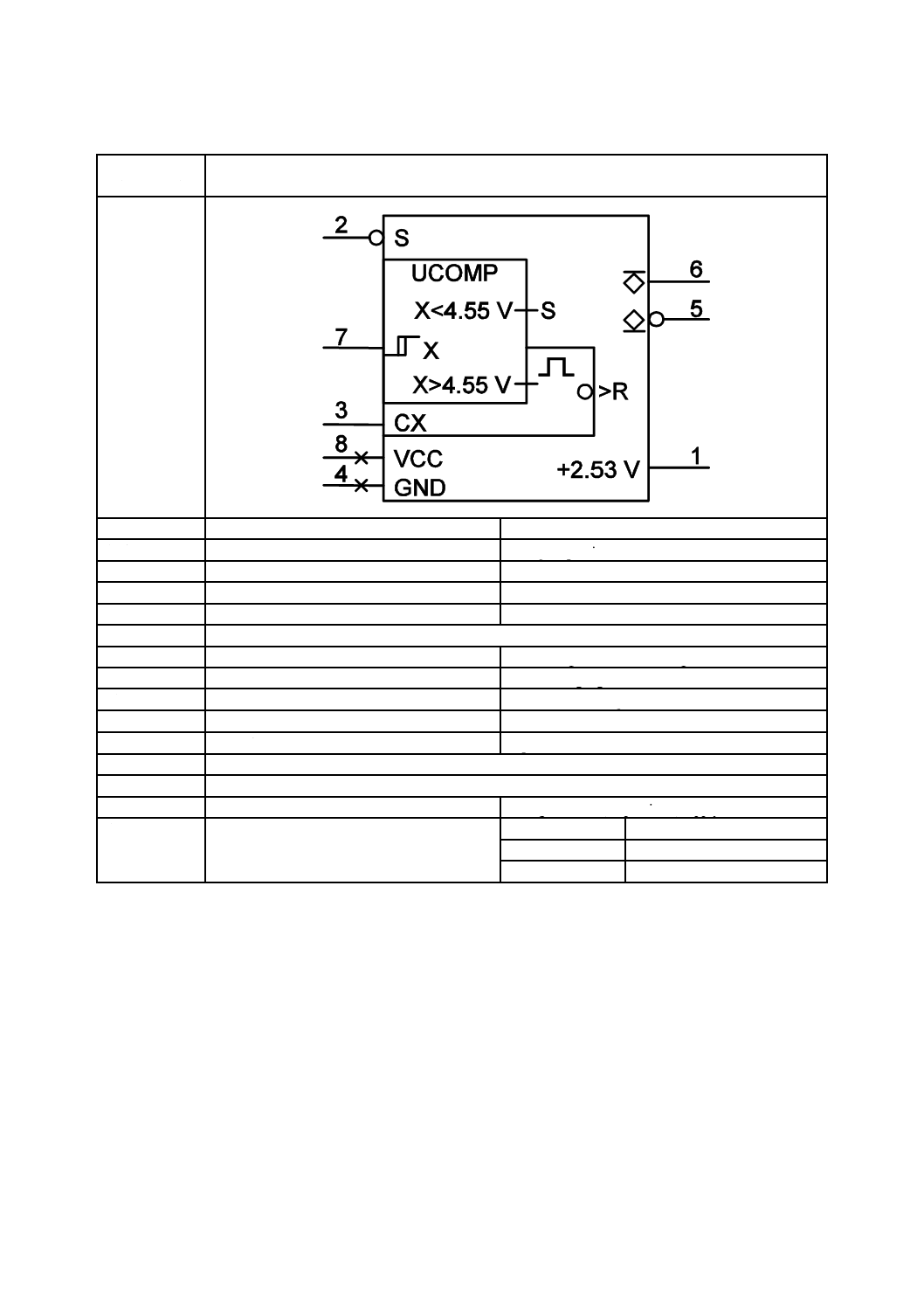
70
C 0617-13:2011
2019年7月1日の法改正により名称が変わりました。まえがきを除き,本規格中の「日本工業規格」を「日本産業規格」に読み替えてください。
第18節 その他のデバイス
図記号番号
(識別番号)
図記号(Symbol)
13-18-01
(S01806)
項目
説明
IEC 60617情報(参考)
名称
電圧監視器
Voltage supervisor
別の名称
−
−
様式
−
−
別様式
−
−
注釈
A00352
適用分類
回路図,機能図
Circuit diagrams, Function diagrams
機能分類
信号又は情報の処理(K)
K Processing signals or information
形状分類
文字,長方形
Characters, Rectangles
制限事項
−
−
補足事項
例えばTL7705 A
E.g. TL7705 A.
適用図記号
S01466,S01475,S01477,S01492,S01494,S01495,S01558,S01560,S01674,S01753,S01800
被適用図記号
−
キーワード
アナログ回路,監視器,電源回路
analogue circuits, supervisors, supply circuits
注記
−
Status level
Standard
Released on
2004-09-13
Obsolete from
−
71
C 0617-13:2011
2019年7月1日の法改正により名称が変わりました。まえがきを除き,本規格中の「日本工業規格」を「日本産業規格」に読み替えてください。
5
注釈
当該図記号の説明及び付加的な関連規定を,次に示す。注釈は通常,複数の図記号で共有されるため,
注釈番号を記した別のページに記載されている。
注釈番号はAnnnnnの形式で示し,nは0〜9の整数で表す。この番号はIEC 60617の注釈(Application
notes)に対応しており,番号付けには意味はない。
注釈番号
注釈
被適用図記号
IEC 60617情報(参考)
A00276
依存関係表記
1 一般的説明
依存関係表記は,全ての素子とその相
互接続を実際には示していない。入力
間,出力間又は入出力間の相互関係を
表記するという意味を示す。
備考−依存関係表記は複合素子に適
用する場合を除き,組合せ論理素子用
図記号の代わりとして用いることは
好ましくない。
依存関係表記がもたらす情報は,素子
の機能面において,限定図記号の情報
を補足する。
依存関係表記では,“影響を与える”
と“影響を受ける”という語句を用い
る。
入力が影響を与えるのか受けるのか
に確証が得られない場合[例えば,そ
れらが論理積AND(AND)関係にあ
る場合]その選択は適宜行ってもよ
い。
複合素子の中には,出力が入力や他の
出力に作用する場合もある。簡単のた
め,2及び3における依存関係表記は
“影響を与える入力”だけを記載して
いるが,その推奨記述は影響を与える
出力にも適用するのが望ましい。
2 通則
依存関係表記は,通常,内部論理状態
間の関係を定義する。3ステート出
力,パッシブプルダウン出力,パッシ
ブプルアップ出力及び開放回路出力
[図記号12-09-03(S01493)〜12-09-08
(S01498)]の場合はイネイブル
(ENABLE)依存関係(A00284)が
影響入力の内部論理状態と被影響出
力の外部状態の関係を定義する。
依存関係表記は,次による。
12-15-01,12-15-02,
12-16-01,12-16-02,
12-17-01,12-17-02,
12-17A-01,
12-17A-02,
12-18-01,12-18-02,
12-19-01,12-19-02,
12-20-01,12-21-01,
12-21-02,12-23-01,
13-05-14,13-05-15,
13-05-21,13-05-22,
13-05-23,13-05-25,
12-14-01,12-14-02
S01550,S01551,
S01552,S01553,
S01554,S01555,
S01556,S01557,
S01558,S01559,
S01560,S01561,
S01562,S01563,
S01564,S01565,
S01766,S01767,
S01773,S01774,
S01775,S01777,
S01810,S01811
Dependency notation
1 General explanation
Dependency notation is a means of denoting the
relationships between inputs, between outputs,
or between inputs and outputs, without actually
showing all the elements and interconnections
involved.
NOTE−Apart from its use in complex
elements, dependency notation should not be
used to replace the symbols for combinative
elements.
The information provided by dependency
notation supplements that provided by the
qualifying symbols for an element's function.
In the convention for dependency notation, use
will be made of the terms "affecting" and
"affected". In the case where it is not evident
which inputs must be considered as being the
affecting or the affected ones (for example, if
they stand in an AND relationship), the choice
may be made in any convenient way.
In some complex elements, outputs may have
an effect on inputs and other outputs. For the
sake of simplicity, the text of sections 2 and 3
refers to "affecting inputs" only, but it should be
understood that the recommended notation
applies to affecting outputs also.
2 Convention
Dependency
notation
usually
defines
relationships between internal logic states.
However, in the case of 3-state outputs,
passive-pull-down
outputs,
passive-pull-up
outputs and open-circuit outputs [symbols
S01493 (12-09-03) through S01498 12-09-08)],
ENABLE
dependency
(A00284)
defines
relationships between the internal logic states of
affecting inputs and the external states of
affected outputs.
Application
of
dependency
notation is
accomplished by
72
C 0617-13:2011
2019年7月1日の法改正により名称が変わりました。まえがきを除き,本規格中の「日本工業規格」を「日本産業規格」に読み替えてください。
注釈番号
注釈
被適用図記号
IEC 60617情報(参考)
A00276
(続き)
− 他の入出力に影響を与える入力
には,その関係を表す特定の文字
記号とそれに続いて識別番号を
ラベル付けする。
− 影響を受ける入出力には,それに
影響を与える影響入力の識別番
号と同一の番号をラベル付けす
る。
影響入力[出力]の内部論理状態と相
補関係にある状態が影響を与える場
合,被影響入力[出力]の識別番号の
上にバーを引かなければならない。
備考−例については図記号12-42-11
(S01669)を参照する。バーを不要に
する記述法については,図記号
12-49-04(S01691)の補足事項を参照。
被影響入出力に,素子に対する作用を
表すラベルを付ける場合,そのラベル
は識別番号の後に付ける。
入力又は出力が複数の影響入力から
影響を受ける場合,各影響入力のコン
マで区切られた識別番号を,被影響入
力又は出力のラベルに表示しなけれ
ばならない。識別番号は影響を与える
順に左から右へ付ける(A00289も参
照)。
異なる文字でラベル付けされた二つ
の影響入力は,一方のラベルがA
(A00287)である場合以外は,同じ
識別番号をもってはならない。
二つの影響入力が同一文字かつ同一
識別番号をもつ場合,それらは互いに
論理和(OR)の関係になる。
被影響入出力の機能が数字で示され
るとき(例えば,コード変換器の出
力),影響入力と被影響入出力の両者
に結びつく識別番号は,あいまいさを
避けるように別の文字で置き換える
(例えばギリシア文字)。
影響入力は,その図記号の対応した
(識別番号で対応づけした)被影響入
出力だけに影響を与える。
3 依存関係の種類
次のような依存関係を定義する。
論理積(AND),論理和(OR),及び
論理否定(NEGATE)依存関係は入出
力間のブール代数の関係を示すため
に用いられる。
− labelling the input affecting other inputs or
outputs with a particular letter symbol
denoting
the
relationship
involved
followed by an identifying number, and
− labelling each input or output affected by
that affecting input with that same number.
If it is the complement of the internal logic state
of the affecting input [output] that does the
affecting, a bar shall be placed over the
identifying number at the affected input
[output].
NOTE−For an example of use, see symbol
S01669 (12-42-11). For a technique avoiding
the use of a bar, see the note with symbol
S01691 (12-49-04).
If the affected input or output requires a label to
denote an effect it has on the element, this label
shall be prefixed by the identifying number of
the affecting input.
If an input or output is affected by more than
one affecting input, the identifying numbers of
each of the affecting inputs shall appear in the
label of the affected one, separated by commas.
The left-to-right order of these identifying
numbers is the same as the sequence of the
affecting relationships (see also section 25).
Two affecting inputs labelled with different
letters shall not have the same identifying
number unless one of the letters is A (see
section 23).
If two affecting inputs have the same letter and
the same identifying number, they stand in an
OR relationship to each other.
If the labels denoting the functions of affected
inputs or outputs must be numbers (for
example, outputs of a coder), the identifying
numbers to be associated with both affecting
inputs and affected inputs or outputs shall be
replaced by another character selected to avoid
ambiguity, for exampie Greek letters.
An
affecting
input
affects
only
the
corresponding affected inputs and outputs of the
symbol.
3 Types of dependency
The following types of dependency are defined.
AND, OR, and NEGATE dependencies are used
to denote Boolean relationships between inputs
and/or outputs.
73
C 0617-13:2011
2019年7月1日の法改正により名称が変わりました。まえがきを除き,本規格中の「日本工業規格」を「日本産業規格」に読み替えてください。
注釈番号
注釈
被適用図記号
IEC 60617情報(参考)
A00276
(続き)
インターコネクション
(INTERCONNECTION)依存関係は
入力又は出力がその論理状態を他の
入出力に強制的に反映することを示
すために用いられる。
トランスミッション
(TRANSMISSION)依存関係は被影
響ポート間の伝送経路の制御を示す
ために用いられる。
コントロール(CONTROL)依存関係
は順序素子のタイミング入力又はク
ロック入力を識別し,どの入力がそれ
によって制御されるかを示すために
用いられる。
セット(SET)依存関係,リセット
(RESET)依存関係はRS双安定素子
のR入力,S入力が両方とも内部状態
1となった場合の内部論理状態を規
定するために用いられる。
イネイブル(ENABLE)依存関係はイ
ネイブル入力を識別するとともに,ど
の入出力がその影響を受けるかを示
すために用いられる(例えば,どの出
力がハイインピーダンス状態になる
かを示すために用いられる)。
モード(MODE)依存関係は素子の動
作モード選択入力を識別するととも
に,入出力がどの動作モードになるか
を示すために用いられる。
アドレス(ADDRESS)依存関係は記
憶素子のアドレス入力を識別するた
めに用いる。
表I(JIS C 0617-12の
“A00276̲Table̲EN”を参照)に種々
の依存関係とその作用をまとめて示
す。
考え方の説明図を用いて,さらに詳細
な定義をA00277〜A00289に示す。説
明図には,次の一般図記号を用いてい
る。
12-27-01(S01566)〜12-27-13(S01578)
12-30-01(S01607)
12-32-01(S01610)
12-34-01(S01623)
12-36-01(S01626)〜12-36-04(S01629)
12-38-01(S01636)〜12-38-08(S01643)
12-40-01(S01655)
INTERCONNECTION dependency is used to
indicate that an input or output imposes its logic
state on one or more other inputs and/or
outputs.
TRANSMISSION dependency is used to
indicate controlled transmission paths between
affected ports.
CONTROL dependency is used to identify a
timing input or a clock input of a sequential
element and to indicate which inputs are
controlled by it.
SET and RESET dependencies are used to
specify the internal logic states of an
RS-bistable element when the R- and S-inputs
both stand at their internal 1-States.
ENABLE dependency is used to identify an
Enable input and to indicate which inputs
and/or outputs are controlled by it (for example
which outputs take on their high-impedance
condition).
MODE dependency is used to identify an input
that selects the mode of operation of an element
and to indicate the inputs and/or outputs that
depend on that mode.
ADDRESS dependency is used to identify the
Address inputs of a memory.
Table I (see A00276̲Table̲EN.pdf below) lists
the various dependencies and summarizes their
effects.
More detailed definitions appear in A00277
through A00289, together with illustrations of
the concepts.
In these illustrations, following general symbols
are used.
S01566 (12-27-01) through S01578 (12-27-13)
S01607 (12-30-01)
S01610 (12-32-01)
S01623 (12-34-01)
S01626 (12-36-01) through S01629 (12-36-04)
S01636 (12-38-01) through S01643 (12-38-08)
S01655 (12-40-01)
74
C 0617-13:2011
2019年7月1日の法改正により名称が変わりました。まえがきを除き,本規格中の「日本工業規格」を「日本産業規格」に読み替えてください。
注釈番号
注釈
被適用図記号
IEC 60617情報(参考)
A00276
(続き)
12-44-01(S01674)及び12-44-02
(S01675)
12-46-01(S01678)〜12-46-05(S01682)
12-48-01(S01685)〜12-48-03(S01687)
12-50-01(S01706)〜12-50-05(S01710)
12-52-01(S01723)
表Iにおいて“アクション”という語
句は,次の意味で用いる。
− その影響入力は,素子の機能に対
して通常定義どおりに作用する。
− その被影響出力は素子の機能に
よって定まる内部論理状態をと
る。
S01674 (12-44-01) and S01675 (12-44-02)
S01678 (12-46-01) through S01682 (12-46-05)
S01685 (12-48-01) through S01687 (12-48-03)
S01706 (12-50-01) through S01710 (12-50-05)
S01723 (12-52-01)
In Table I, the word "action" implies
− that affecting inputs will have their
normally defined effect on the function of
the element;
− that affected outputs will take on the
internal logic States determined by the
function of the element.
A00281
トランスミッション
(TRANSMISSION)依存関係(X依
存関係)
トランスミッション
(TRANSMISSION)依存関係は,被
影響ポート(入力,出力,及び/又は
入出力)相互間の伝送経路の制御を示
すために用いる。伝送経路は他に指示
がない限り双方向であるトランスミ
ッション(TRANSMISSION)依存関
係は単純なアナログスイッチの図記
号化を可能にする。したがって,より
記述が複雑なデバイスもこれをすれ
ば簡単に記述できる。
JIS C 0617-12の
“A00281̲Illustration̲EN”を参照。
12-17A-01,
12-17A-02,
13-05-25,13-17-01,
13-17-02
S01556,S01557,
S01777,S01804,
S01805
TRANSMISSION dependency
(X-dependency)
TRANSMISSION dependency is used to
indicate controlled transmission paths between
affected
ports
(inputs,
outputs
and/or
input-outputs). Unless otherwise indicated, the
transmission paths are bidirectional. The
TRANSMISSION dependency provides a way
of symbolizing simple analogue switches and it
enables more complicated devices to be
depicted in a concise manner.
See A00281̲Illustration̲EN.pdf
A00289
入力及び出力におけるラベルの順序
1 入力におけるラベルの順序
1.1 図記号12-09-47(S01540),
12-09-08(S01498),12-09-02(S01492)
のうち,幾つかを同時に表記する場合
は,入力線から記号枠の内側へ
12-09-47(S01540),12-09-08(S01498),
12-09-02(S01492)の順に並べる。こ
れらの図記号は,入力線と入力限定図
記号(例えば,依存関係表記)の間に
表記しなければならない。
説明図については,JIS C 0617-12の
“A00289̲Illustration̲a̲EN”参照。
12-09-03,12-15-01,
12-15-02,12-16-01,
12-16-02,12-17-01,
12-17-02,
12-17A-01,
12-17A-02,
12-18-02,12-19-01,
12-19-02,12-20-01,
12-21-01,12-21-02,
12-23-01,13-05-14,
13-05-15,13-05-21,
13-05-22,13-05-23,
13-05-25,12-14-01,
12-14-02
The ordering of labels associated with inputs
and with outputs
1 Order of input labels
1.1 If one or more of the symbols S01540
(12-09-47), S01498 (12-09-08) and S01492
(12-09-02) are required at an input, they shall
be shown, as needed, in that order [S01540
(12-09-47),
S01498
(12-09-08),
S01492
(12-09-02)] reading from the input towards the
interior of the element. These symbols shall be
drawn between the input line(s) and any
input-qualifying
symbol,
for
example,
dependency notation.
For an illustration, see
A00289̲Illustration̲a̲EN.pdf below.
75
C 0617-13:2011
2019年7月1日の法改正により名称が変わりました。まえがきを除き,本規格中の「日本工業規格」を「日本産業規格」に読み替えてください。
注釈番号
注釈
被適用図記号
IEC 60617情報(参考)
A00289
(続き)
1.2 一つの機能をもつ入力が他の入
力から影響を受ける場合,その機能に
対する限定図記号を影響入力の識別
番号に続いて表示すること。識別番号
は,作用する順序に対応して左から右
への順に示すこと。番号と番号の間
は,コンマで区切る。この場合,影響
を与える入力又は出力(個別に考える
こと)のうちどれか一つでも被影響入
力を無効にするものがあれば,その被
影響入力はなにも作用しない。
説明図については,JIS C 0617-12の
“00289̲Illustration̲b̲EN”を参照。
1.3 一つの入力が複数の機能又は複
数の影響入力のラベルの組をもつ場
合,それらの機能又はラベルの組は
別々の入力線上に表記し,記号枠の外
側で結線してもよい[例として,図記
号12-33-07(S01619),12-49-11
(S01698),12-49-15(S01702)参照)]。
もし,この表現方法が芳しくない場合
は,異なるラベルの組を斜線で区切っ
て一つの入力に表示してもよい。この
場合はラベルの組の順序には意味が
ない。入力の複数機能のうちの一つが
入力ラベルなしで表される場合は,他
の機能を表す入力ラベルの組の先頭
に斜線を配置すること[例として,図
記号12-49-13(S01700)参照]。
説明図については,JIS C 0617-12の
“A00289̲Illustration̲c”を参照。
1.4 もし組合せ論理素子の全ての入
力が無効(素子の機能に対してなにも
作用しない)なら,その素子の出力の
内部論理状態はこの図記号では規定
されない。もし,順序論理素子の全て
の入力が無効(素子の機能に対してな
にも作用しない)なら,この素子の内
容は変化せず,出力は既存の内部論理
状態を保持する。
1.5 ラベルは代数的手法を用いて展
開してもよい。
説明図については,JIS C 0617-12の
“A00289̲Illustration̲d”を参照。
S01493,S01550,
S01551,S01552,
S01553,S01554,
S01555,S01556,
S01557,S01559,
S01560,S01561,
S01562,S01563,
S01564,S01565,
S01766,S01767,
S01773,S01774,
S01775, S01777,
S01810,S01811
1.2 If an input exerting a single function is
affected by other inputs, the qualifying symbol
for that function shall be preceded by the
identifying numbers of the affecting inputs. The
left-to-right order of these identifying numbers
shall be the order in which the effects or
modifications must be applied. The affected
input exerts no function if the logic state of any
one of the affecting inputs or outputs,
considered separately, would cause the affected
input to have no effect, regardless of the logic
states of other affecting inputs.
For an illustration, see
A00289̲Illustration̲b̲EN.pdf below.
1.3 If an input exerts more than one function
or has more than one set of labels of affecting
inputs, the indications of these functions or
these sets may be shown on different input
lines, which must be connected together outside
the outline [see examples S01619 (12-33-07),
S01698
(12-49-11),
S01702
(12-49-15)].
However, there are cases in which this method
of presentation is not advantageous. In those
cases, the input may be shown once with the
different sets of labels separated by solidi. No
meaning is attached to the order of these sets of
labels. If one of the functional effects of an
input is that of an unlabelled input of the
element, a solidus shall precede the first set of
labels shown [see, for example, symbol S01700
(12-49-13)].
For illustrations, see
A00289̲Illustration̲c.pdf below.
1.4 If all inputs of a combinative element are
disabled (caused to have no effect on the
function of the element), the internal logic
states of the outputs of the element are not
specified by the symbol. If all inputs of a
sequential element are disabled (caused to have
no effect on the function of the element), the
content of this element is not changed and the
outputs remain at their existing internal logic
states.
1.5 Labels may be factored using algebraic
techniques.
For illustrations, see
A00289̲Illustration̲d.pdf below.
76
C 0617-13:2011
2019年7月1日の法改正により名称が変わりました。まえがきを除き,本規格中の「日本工業規格」を「日本産業規格」に読み替えてください。
注釈番号
注釈
被適用図記号
IEC 60617情報(参考)
A00289
(続き)
1.6 一般に,入力において,ビット
グループ化図記号の左側にある依存
関係表記は,コード変換器の入力に適
用する。また,ビットグループ化図記
号の後にある依存関係表記は,コード
変換器の出力が接続される入力に適
用する。ただし,記憶付き入力につい
ては,1.7を参照。
説明図については,JIS C 0617-12の
“A00289̲Illustration̲e”を参照。
1.7 全ての入力にレジスタをもつ組
合せ論理素子は,全ての出力にレジス
タをもつ組合せ論理素子と機能的に
等価である。
説明図については,JIS C 0617-12の
“A00289̲Illustration̲f”を参照。
すなわち,次の素子Aは素子Bと機
能的に等価である。
上記によって,入力の記憶は,A00288
の第3節で定義したように“mD”で
表記してもよい。この場合,“mD”は
ビットグループ化図記号と記憶付き
入力を表す図記号の間に表記しても
よいし,入力に直接表記してもよい。
説明図については,JIS C 0617-12の
“A00289̲Illustration̲g”を参照。
2 出力におけるラベルの順序
2.1 出力が複数の異なるラベルをも
つ場合,それが影響入出力の識別番号
であるかどうかにかかわらず,これら
の順序は次による。
−延期出力の図記号12-09-01
(S01491)があれば最初に記入する。
ただし,その出力に関連する入力の明
示が必要なときは,延期出力の図記号
の前にその入力の識別記号又は番号
を記入する。
−続いて,出力の内部論理状態を決定
又は変更する限定図記号を記入する。
この場合,作用する順序に従って,左
から右の順序とする。応用例について
は,図記号12-49-15(S01702)を参照。
1.6 In general, dependency notation shown at
the inputs to the left of the bit-grouping symbol
applies to the inputs of the coder, and
dependency
notation
shown
after
the
bit-grouping symbol applies to the inputs fed by
the outputs of the coder. However, for inputs
with inherent storage, see 1.7.
For illustrations, see
A00289̲Illustration̲e.pdf below.
1.7 Any combinatorial logic element together
with a storage register on all its inputs is
functionally equivalent to that same element
together with a storage register on its outputs.
For an illustration, see
A00289̲Illustration̲f.pdf below.
Thus element A of the illustration is
functionally equivalent to element B.
Because of this, inherent storage at an input
may be indicated by placing the "mD", as
defined in clause 3 of A00288, either between
the bit-grouping symbol and the symbol
denoting the function of the stored input, or
directly at the inputs.
For an illustration, see
A00289̲Illustration̲g.pdf below.
2 Order of output labels
2.1 If an output has a number of different
labels, regardless of whether they are
identifying numbers of affecting inputs or
outputs or not, these labels shall be shown in
the following order:
−if the postponed output symbol (S01491
(12-09-01)) has to be shown, this comes first, if
necessary preceded by the indications of the
inputs to which it must be applied;
−followed by the qualifying symbols
determining or modifying the internal logic
state of the output, such that the left-to-right
order of these labels correspond to the order in
which their effects must be applied. For
application, see symbol S01702 (12-49-15);
77
C 0617-13:2011
2019年7月1日の法改正により名称が変わりました。まえがきを除き,本規格中の「日本工業規格」を「日本産業規格」に読み替えてください。
注釈番号
注釈
被適用図記号
IEC 60617情報(参考)
A00289
(続き)
−続いて,入力及び他の出力に対す
る,その出力の作用を表すラベルを記
入する。
開放回路出力,パッシブ・プルダウン,
パッシブ・プルアップ及び3ステート
出力及び特殊増幅(ドライブ能力)の
図記号は,これらの図記号[12-09-03
(S01493)〜12-09-08A(S01499)参
照]に示したように,各々出力線に近
接して示す。
一つの出力に対して論理和(OR)の
関係にある複数のラベルが必要な場
合(例えば,その出力がアクションの
モードに依存して異なる影響を受け
るような場合)には,それらのラベル
の組は別々の出力線に表記し,記号枠
の外側で結線してもよい。この場合,
見やすさが損なわれるようであれば,
異なるラベルの組を斜線で区切って
一つの出力に表示してもよい。
ラベルの組の中に二つの影響入力の
識別番号が隣接しており,数字以外の
文字で分離されていない場合は,コン
マを用いて分離する(A00276を参
照)。
説明図については,JIS C 0617-12の
“A00289̲Illustration̲h”を参照。
2.2 ラベルは代数的手法を用いて展
開してもよい。
説明図については,JIS C 0617-12の
“A00289̲Illustration̲j”を参照。
2.3 出力用ビットグループ化の図記
号12-09-25(S01517)を用いる場合,
グループ化対象出力のラベルの組が,
重み表示を除いて同一ならば,そのラ
ベルの組を,アスタリスク[図記号
12-09-25(S01517)で他の図記号に置
き換える部分]とグループ化を表す図
記号の間に記述してもよい。
なお,このラベルの組は開放出力,パ
ッシブ・プルダウン,パッシブ・プル
アップ,3ステート出力及び特殊増幅
(ドライブ能力)の図記号[12-09-03
(S01493)〜12-09-08A(S01499)]を
含んでもよい。この場合,グループ化
を表す図記号と重み表示を除いた部
分のラベルの順序が変わらないよう
に記述する。
説明図については,JIS C 0617-12の
“A00289̲Illustration̲k̲EN”を参照。
−followed by the label indicating the effect of
the output on inputs and other outputs of the
element.
Symbols for open-circuit, passive-pull-down,
passive-pull-up and 3-state outputs, and outputs
with special amplification (drive capability)
shall each be drawn adjacent to their output
lines as described with these symbols (S01493
(12-09-03) ... S01499 (12-09-08A)).
If an output needs several different sets of
labels which can be considered to stand in an
internal
OR relationship (for
example,
depending on the mode of action), these sets
may be shown on different output lines which
must be connected together outside the outline.
However, there are cases in which this method
of presentation is not advantageous. In those
cases the output may be shown once with the
different sets of labels separated by solidi.
Two adjacent identifying numbers of affecting
inputs in a set of labels not already separated by
a non-numeric character shall be separated by a
comma (see A00276).
For illustrations, see
A00289̲Illustration̲h.pdf below.
2.2 Labels may also be factored using
algebraic techniques.
For illustrations, see
A00289̲Illustration̲j.pdf below.
2.3 If the bit grouping symbol for outputs
[symbol S01517 (12-09-25)] is used and the
sets of labels of all outputs grouped together
differ only in the indications of the weights, the
sets of labels, including the symbols for
open-circuit,
passive-pull-down,
passive-pull-up and 3-state outputs, and outputs
with special amplification (drive capability)
[symbols S01493 (12-09-03) ... S01499
(12-09-08A)] but excluding the indications of
the weights, may be shown only once between
the symbol replacing the asterisk and the
grouping symbol, provided that, except for the
grouping symbol and the weights, the proper
order of the labels is maintained.
For an illustration, see
A00289̲Illustration̲k̲EN.pdf below.

78
C 0617-13:2011
2019年7月1日の法改正により名称が変わりました。まえがきを除き,本規格中の「日本工業規格」を「日本産業規格」に読み替えてください。
注釈番号
注釈
被適用図記号
IEC 60617情報(参考)
A00296
コーダ,コードコンバータ
1 コード変換器における入力と出力
との関係
1.1 一般限定図記号における入出力
コードの表示
このコード変換の表示方法は,次の規
則に基づくものとする。
入力コードに基づいて,そのときの入
力の内部状態によって決まるコード
変換器の内部値(又は等価なもの)を,
出力コードに対応して,出力の内部論
理状態に変換,再生する。
入力の内部論理状態と内部値の関係
は,次のいずれかの方法で表示する。
−入力に数字を付け,内部状態1の入
力の示す数字の和を,変換器の内部値
として表す。又は
−Xを,入力コードを示す適切な表記
で置き換え,入力にそのコード特性に
関する文字をラベル付けする。
出力の内部論理状態と内部値の関係
は,次のいずれかの方法で表示する。
−各出力に,内部状態を1にする全て
の内部値を表す数字を付ける。これら
の数字は,斜線で区切って示す。Yを
依存関係の種類を示す文字で置き換
えてもよい(JIS C 0617-12の注釈
A00288参照)。出力の内部状態を1
にする内部数が連続しているときは,
最初の数と最後の数の間に3個の点
を入れて表してもよい。例えば,4...
9=4/5/6/7/8/9。又は
−Yを出力コードを表す適切な表記
で置き換え,出力にこのコードに関連
する文字をラベル付けする。
説明図については,JIS C 0617-12の
“A00296̲Illustration̲a̲EN”を参照。
備考−一般限定図記号BIN/6を,X/Y
の代わりに用いてもよい。1.1.1及び
1.1.2を参照。
12-32-01,12-33-01,
13-10-01
S01610,S01611,
S01791
Coders, code converters
1 Relationships between inputs and outputs of
coders
1.1 Indication of input and output codes in the
general qualifying symbol
This method of indicating code conversion is
based on the following rule:
Depending on the input code, the internal logic
states of the inputs determine an internal value
(or its equivalent). This internal value is
reproduced by the internal logic states of the
outputs, depending on the output code.
The relationships between the internal logic
states of the inputs and the internal value shall
be indicated in one of the following ways:
−label the inputs with numbers, in which case
the internal value equals the sum of the
numbers associated with those inputs that stand
at their internal 1- states; or
−replace X by an appropriate designation of
the input code and label the inputs with
characters that refer to this code.
The relationships between the internal value
and the internal logic states of the outputs shall
be indicated in one of the following ways:
−label each output with a list of numbers
representing the internal values that lead to the
internal 1-state of that output. These numbers
shall be separated by solidi. This method may
also be applied when Y is replaced by a letter
denoting a type of dependency (see also
A00288). If a continuous range of internal
values produces the internal 1-state of an
output, this can be indicated by two numbers
that are inclusively the beginning and the end of
the range, with these two numbers separated by
three dots, for example, 4 ... 9 = 4/5/6/7/8/9; or
−replace Y by an appropriate indication of the
output code and label the outputs with
characters that refer to this code.
For illustrations, see
A00296̲Illustration̲a̲EN.pdf below.
NOTE−Alternatively, the general qualifying
symbol BIN/6 may be used instead of X/Y. See
1.1.1 and 1.1 2
79
C 0617-13:2011
2019年7月1日の法改正により名称が変わりました。まえがきを除き,本規格中の「日本工業規格」を「日本産業規格」に読み替えてください。
注釈番号
注釈
被適用図記号
IEC 60617情報(参考)
A00296
(続き)
X又はYを特定コードの表示と置き
換える場合には,さらに,次の規則を
適用する。
以下,次の3種類のコードについて説
明する。
−合計コード,
−直接表示コード,及び
−識別コード。
1.1.1 合計コード
これらのコード,例えば,“X”には,
内部状態1を表す入力[出力]の重み
の合計に対応する内部数値が存在す
る。
入力[出力]の内部論理状態と,内部
値との関係の表示は限定図記号のX
[Y] を入力[出力]コードの該当する
表示で置き換える。さらに,それらの
個々の重みを示している数値で,入力
[出力]にラベル付けする。
次の合計コードを定義する。
−BIN 二進コード
個々の重みが全て2の累乗である数
字コード。
入力[出力]は,十進又は,累乗の指
数(十進表記)でラベル付けする。
−BCD 8-4-2-1 二進化十進数
10進表現コードで,十進各けたを4
ビットの二進数(重みは8,4,2,1)
で表す。
例については,JIS C 0617-12の
“A00296̲Example̲a̲EN”を参照。
入力[出力]は,例えば,1,2,4,8,
10,20などのような十進の重みでラ
ベルを付けること。
備考−4入力の組に9(×10n)を上回
るコードが入力されると,内部値が出
力値よりも多くのけたが必要となる
ため,素子の振る舞いは図記号によっ
て規定されない。出力のけた数以上の
内部値が要求された場合,素子の振る
舞いは図記号によって規定されない。
If X or Y is replaced by an indication of a
specific code, further rules apply.
In the following text, the codes are subdivided
into three categories:
−summing codes,
−direct-indication codes, and
−identification codes.
1.1.1 Summing Codes
With these codes, like "X", there is an internal
numeric value that corresponds to the sum of
the weights of the inputs [outputs] that stand at
their internal
1-states.
The indication of the relationships between the
internal logic states of the inputs [outputs] and
the internal value shall be accomplished by
replacing X [Y] of the qualifying symbol with
an appropriate indication of the input [output]
code and by labelling the inputs [outputs] with
numbers indicating their individual weights.
The following summing codes are defined:
−BIN Binary code
The number code in which the individual
weights are all powers of 2. Inputs [outputs]
shall be labelled either with decimal weights or
with decimal exponents of the powers of 2.
−BCD 8-4-2-1 Binary-coded decimal
The number code in which each digit in the
decimal representation of a number is encoded
as a binary number in 4 bits with the relative
weights of 8, 4, 2, and 1.
For an example, see
A00296̲Example̲a̲EN.pdf below.
Inputs [outputs] shall be labelled with decimal
weights, for example 1, 2, 4, 8, 10, 20, etc.
NOTE−For inputs, the behaviour of the
element is unspecified by the symbol if the
internal value produced by any set of four
inputs exceeds 9 (x10^n).
For outputs, the behaviour of the element is
unspecified by the symbol if the internal value
requires more digits than are provided at the
outputs.
80
C 0617-13:2011
2019年7月1日の法改正により名称が変わりました。まえがきを除き,本規格中の「日本工業規格」を「日本産業規格」に読み替えてください。
注釈番号
注釈
被適用図記号
IEC 60617情報(参考)
A00296
(続き)
−X-3 3増しコード
十進表現コードで十進各けたを4入
力[出力]で表し,その内部数を4
ビットの二進数より3(×10n)小さ
い数としたもの。BCDの備考を参照。
説明図については,JIS C 0617-12の
“A00296̲Illustration̲b̲EN”を参照。
無効なBCDコード,すなわち,9よ
り大きな内部値を生じるような場合,
結果として生じる出力状態は,この図
記号では規定されない。もし,BIN/Y
を一般限定図記号として扱う場合は,
9より大きな内部値の場合,出力は内
部状態0を表すことになる。
−2CMPL 2の補数コード
範囲−2k+n−1≦y≦2k+n−1−2kを満た
す数字yを意味しているnビットの数
字コード(xn−1,...,x0)(整数に対
して,k=0。固定小数点の小数部に対
して,kは負である。)。
X0〜Xn−2の個々の重みは,2の累乗
(2k〜2k+n−2)である。付加ビット(Xn
−1)は,−2k+n−1を示す。個々のビッ
トの値とyの値の関係は,次のように
表すことができる。
y=−2k+n−1xn−1+Σ2k+1x1によって表
すことができる。
負の[正の]数字は,対応する正の[負
の]数字の1の補数(論理補数)と
2kとの和として表される。
例については,JIS C 0617-12の
“A00296̲Example̲b̲EN”を参照。
入力[出力]は,正の十進の重みか,
最高次数(符号)ビットを含む2の累
乗の指数でラベル付けする。
説明図については,JIS C 0617-12の
“A00296̲Illustration̲c”を参照。
−X-3 Excess-three code
The BCD code in which the internal value of
each 4 inputs [outputs] is 3 (X10^n) less than
the sum of those inputs [outputs]. See note to
BCD.
For illustrations, see
A00296̲Illustration̲b̲EN.pdf below.
For invalid BCD codes, that is, those that would
produce an internal value greater than 9, the
resulting output states are not specified by this
symbol. If the general qualifying symbol were
BIN/Y, then the symbol would show that all
outputs stand at the internal 0-state for internal
values greater than 9.
−2CMPL Twos complement code
The n-bit number code (xn-1, ..., x0) 2^k+n-1
-2^k. (For
y representing a number y in the
range -2^k+n-1 integers, k = 0. For
fixed-point fractions, k is negative.)
The individual weights of x0 through xn-2 are
powers of 2(2^k through 2^k+n-2). The
additional bit (xn-1,) indicates -2^k+n-1. The
relationship between the values of the
individual bits and y 2^k+i xi can be expressed
by y = -2^k+n-1 xn-1, +
A negative [positive] number is represented by
2^k
plus
the
oneʼs-complement
(logic
complement) of the corresponding positive
[negative] number.
For an example, see
A00296̲Example̲b̲EN.pdf below.
Inputs [outputs] shall be labelled either with
positive decimal weights or with exponents of
the powers of 2 including the highest order
(sign) bit.
For an illustration, see
A00296̲Illustration̲c.pdf below.
81
C 0617-13:2011
2019年7月1日の法改正により名称が変わりました。まえがきを除き,本規格中の「日本工業規格」を「日本産業規格」に読み替えてください。
注釈番号
注釈
被適用図記号
IEC 60617情報(参考)
A00296
(続き)
1.1.2 直接表示コード
これらのコード,例えば,“Y”では,
内部値と入力[出力]の内部論理状態
との関係は限定図記号のX [Y] を入
力[出力]コードの該当する表示で置
き換えて示す。
さらに,内部値を表す数字で入力にラ
ベル付けするか,出力に,その出力の
内部論理状態が1になる内部値を表
す数字のリストをラベル付けする。こ
れらの数字は,斜線で区切る。
もし内部値の連続範囲が,出力の内部
状態を1にする場合は,最初と最後の
二つの数字を用い,これらの二つの数
字の間を3個の点で分離して示して
もよい。例えば,4. ..9=4/5/6/7/8/9。
次のようにコードを定義する。
−m状態をもつ一般コード(mは,数
字で置き換える)
内部論理状態のm個の組合せによっ
て入力又は出力を定義するコード。
−HPRI 最高優先入力コード
もし複数の入力が,内部状態1にある
とき,最も高い重みをもつ入力が優先
される。どの入力も内部状態1でない
ならば,内部値はゼロである。
−DEC 十進コード
10の入力[出力]が存在して,0〜9
の重みをもつコード。
備考−ゼロの重みをもつ入力[出力]
が省略される場合は,ゼロの内部値
は,全ての入力[出力]の内部状態が
0の場合に対応する。
−OCT 八進コード
8入力[出力]が存在して,0〜7の重
みをもつコード。
DECに対する備考を参照。
1.1.2 Direct-indication codes
With these codes, like "Y", the relationship
between the internal numeric value and the
internal logic state of each input [output] shall
be indicated by replacing X [Y] of the
qualifying
symbol
with
an
appropriate
indication of the input [output] code and by
labelling each input with a number indicating
the internal value produced, or by labelling each
output with a list of numbers indicating those
internal values that lead to the internal 1-state of
that output.
These numbers shall be separated by solidi.
If a continuous range of internal values
produces the internal 1-state of an output, this
may be indicated by two numbers that are
inclusively the beginning and the end of the
range, with these two numbers separated by
three dots, for example:
4 ... 9 = 4/5/6/7/8/9.
The following codes are defined:
−m General code with m states (m shall be
replaced by a number)
A code in which m combinations of internai
logic states are defined for inputs or possibly
for outputs.
−HPRI Highest-priority input code
An input code in which the input with the
highest weight takes priority if more than one
input stands at its internal 1-state. If no input
stands at its internal
7-state, the internal value is zero.
−DEC Decimal code
The code in which 10 inputs [outputs] exist and
have the weights 0 through 9.
NOTE−If the input [output] with the weight of
zero is omitted, the internal value of zero
corresponds to all inputs [outputs] standing at
their internal 0- states.
−OCT Octal code
The code in which 8 inputs [outputs] exist and
have the weights 0 through 7. See note to DEC.
82
C 0617-13:2011
2019年7月1日の法改正により名称が変わりました。まえがきを除き,本規格中の「日本工業規格」を「日本産業規格」に読み替えてください。
注釈番号
注釈
被適用図記号
IEC 60617情報(参考)
A00296
(続き)
−HEX 十六進コード
16の入力[出力]が存在して,0〜15
の重みをもつコード。DECに対する
備考を参照。
HPRIを除いて,これらのコードを入
力に適用する場合,複数の入力が内部
状態1であるときの素子の振る舞い
はこの図記号では規定されない。
説明図については,JIS C 0617-12の
“A00296̲Illustration̲d̲EN”を参照。
1.1.3 識別コード
これらのコードには,内部数値はな
い。各入力[出力]パターンは,図記
号(例えば,文字“E”)又は他の対
象を,コード体系に従って識別する。
内部数値に相当するのは,入力[出力]
パターンによって識別される図記号
又は対象である。これらのコードの例
には,ISO Latin-1,ASCII,EBCDIC
及び7セグメントなどがある。内部の
図記号又は対象と各入力[出力]の内
部論理状態の関係は,限定図記号のX
[Y] を入力[出力]コードの適切な表
示で置き換えて示す。各入力[出力]
に,コード中でのビット位置の適切な
表示をラベル付けする
図記号を識別するコードと内部数値
に関連するコードの両方を用いるコ
ード変換器では,両者の変換は内部数
値を十進で表現して図記号に対応さ
せることを基本とする。図記号表現が
ないコードの値についての,素子の振
る舞いは,図記号によって規定されな
い。
説明図については,JIS C 0617-12の
“A00296̲Illustration̲e”を参照。
−HEX Hexadecimal code
The code in which 16 inputs [outputs] exist and
have the weights 0 through 15. See note to
DEC.
Except for HPRI, if these codes are used for
inputs and more than one input stands at its
internal l-state, the behaviour of the element is
not specified by the symbol.
For illustrations, see
A00296̲Illustration̲d̲EN.pdf below.
1.1.3 Identification codes
With these codes there is no internal numeric
value. Instead, each input [output] pattern
identifies a symbol (for example the letter "E")
or other object according to a named coding
scheme. The equivalent of the internal numeric
value is the symbol or object identified by the
input [output] pattern.
Examples of these codes are ISO Latin-1,
ASCII,
EBCDIC,
and
7-segment.
The
relationship between the internal symbol or
object and the internal logic state of each input
[output] shall be indicated by replacing X [Y]
of the qualifying symbol with an appropriate
indication of the input [output] code and by
labelling each input [output] with an
appropriate indication of its bit position within
the code.
If a code identifying a symbol is used in a coder
together with a code that is associated with
internal numeric values, the conversion to or
from these codes is based on the symbolic
decimal representation of those internal
numeric values. If there is no symbolic
representation for a value in the code, the
behaviour of the element for that value is
unspecified by the symbol for the element.
For an illustration, see
A00296̲Illustration̲e.pdf below.
83
C 0617-13:2011
2019年7月1日の法改正により名称が変わりました。まえがきを除き,本規格中の「日本工業規格」を「日本産業規格」に読み替えてください。
注釈番号
注釈
被適用図記号
IEC 60617情報(参考)
A00296
(続き)
1.2 コード表の使用
前に定義したコード及びラベル付け
の代わりの方法として,一般限定図記
号X/Y(又は,他のより適切な限定図
記号)と,入出力関係を示す表の参照
を同時に用いてもよい[例えば,図記
号12-33-09(S01621)参照]。この場
合入力[出力]と表は,例えば,端子
番号を用いるなど,便利な方法で対応
付けすればよい。ただし,この場合,
他の方法と混同されるおそれのある
内部ラベルは用いるべきでない。
説明図については,JIS C 0617-12の
“A00296̲Illustration̲f̲EN”を参照。
2 入力コード又は出力コード以外の
表示による,X及びYの置換え
2.1 コード変換器の内部値は,他の
意味,例えば,カウンタの内容,マル
チポジションスイッチの位置などに
よって与えられる場合がある。このよ
うな場合,Xはその意味が把握できる
適切な表示によって置き換える。
説明図については,JIS C 0617-12の
“A00296̲Illustration̲g̲EN”を参照。
2.2 コード変換器の内部値として,
表示器,素子の内容とみなされる値又
は算術演算の結果値などが考えられ
る。このような場合,Yは,それらの
機能を表す一般限定図記号によって
置き換える。
説明図については,JIS C 0617-12の
“A00296̲Illustration̲h̲EN”を参照。
2.3 内部レジスタがあるような場
合,必要に応じて,入力コードと出力
コードの両方をレジスタの種類に加
えて明記してもよい。この場合,レジ
スタの種類を挟むように入出力コー
ドを配置する。例えば,
“BCD/CTRDIVlOO/BIN”とする。
説明図については,JIS C 0617-12の
“A00296̲Illustration̲j̲EN”を参照。
1.2 Use of coding tables
As an alternative to the use of the previously
defined codes and labelling, the general
qualifying symbol X/Y (or another, more
appropriate, qualifying symbol) may be used
together with an appropriate reference to a table
(as, for example, in symbol S01621 (12-33-09))
in which the relationship between the inputs
and outputs is indicated. The correspondence
between inputs [outputs] and the columns in the
table may be given in any convenient way, for
example by using terminal designations. In this
case, any internal labelling that might be
confused with that arising in one of the other
methods shall be avoided.
For an illustration, see
A00296̲Illustration̲f̲EN.pdf below.
2 Replacement of X and Y by indications
other than designations of the input code or the
output code
2.1 The internal value of a coder may also be
produced by other means, for example by a
counter whose content is the internal value, by a
multi-position switch whose position produces
the internal value, etc. In such cases, the X shall
be replaced by an appropriate indication of the
means involved.
For illustrations, see
A00296̲Illustration̲g̲EN.pdf below.
2.2 The internal value of a coder may also be
represented by a visual display or be regarded
as a value to become the content of an element
or as a value on which a mathematical operation
is performed. In such cases, the Y shall be
replaced by the general qualifying symbol of
the function involved.
For an illustration, see
A00296̲Illustration̲h̲EN.pdf below.
2.3 It may be necessary, especially if an
internal register is involved, to specify both an
input code and an output code in addition to the
type of register found in between the inputs and
outputs, for example, "BCD/CTRDIV1OO/BIN".
For an illustration, see
A00296̲Illustration̲j̲EN.pdf below.
84
C 0617-13:2011
2019年7月1日の法改正により名称が変わりました。まえがきを除き,本規格中の「日本工業規格」を「日本産業規格」に読み替えてください。
注釈番号
注釈
被適用図記号
IEC 60617情報(参考)
A00321
アナログ信号とディジタル信号を区
別する必要がある場合,図記号∩及
び#(JIS C 0617-2の図記号02-17-08
及び02-17-09)を用いなければなら
ない。機能又は信号がディジタルで
あるかアナログであるかについて混
乱を生じるおそれのある場合,これ
らの図記号を,一般限定図記号に付
加するか,又は内部接続を表す図記
号(JIS C 0617-12の図記号12-08-01
(S01475),12-08-01A(S01476),
12-08-05(S01479),12-08-05A
(S01480),12-08-06(S01481)及び
12-08-06A(S01482)の近くに表示し
てもよい。
13-04-01,13-04-02,
13-04-03,13-04-04,
13-04-05,
13-05-16,13-05-17,
13-05-18,13-05-19,
13-05-20,13-05-21,
13-05-22,13-05-23,
13-05-24,13-05-25
S01748,S01749,
S01750,S01751,
S01752,S01768,
S01769,S01770,
S01771,S01772,
S01773,S01774,
S01775,S01776,
S01777
The symbol ∩ (S00216) and # (S00217) shall
be used when it is necessary to distinguish
between analogue and digital signals. They
may also be added to a general qualifying
symbol or placed adjacent to symbols for
internal connections (S01475, S01479 and
S01481) if confusion is likely regarding
whether the function or signal is digital or
analogue.
A00322
混乱を生じなければ,必要な補助情
報をこの節で規定する図記号に追加
してもよい。
13-05-01,13-05-02,
13-05-03,13-05-04,
13-05-05,13-05-07,
13-05-08,13-05-09,
13-05-10,13-05-11,
13-05-12,13-05-13,
13-05-14,13-05-15,
13-05-16,13-05-17,
13-05-18,13-05-19,
13-05-20
S01753,S01754,
S01755,S01756,
S01757,S01759,
S01760,S01761,
S01762,S01763,
S01764,S01765,
S01766,S01767,
S01768,S01769,
S01770,S01771,
S01772
Any necessary supplementary information
may be added to the symbol, provided no
confusion is likely.
A00323
“A00323̲Illustration̲EN”を参照。 13-06-01
S01778
Elements performing mathematical functions
For illustrations, see
A00323̲Illustration̲EN.pdf below.
A00325
増幅器説明図については,
“A00325̲Illustration̲EN”を参照。
13-08-01
S01781
Amplifiers
For illustrations, see
A00325̲Illustration̲EN.pdf below.
A00327
変換器説明図については,
“A00327̲Illustration̲EN”を参照。
13-10-01
S01791
Converters
For illustrations, see
A00327̲Illustration̲EN.pdf below.
A00328
“A00328̲Illustration”を参照。
13-11-04
S01795
For an illustration, see
A00328̲Illustration.pdf below.
A00330
説明図については,
“A00330̲Illustration”を参照。
13-13-02
S01798
For an illustration, see
A00330̲Illustration.pdf below.
85
C 0617-13:2011
2019年7月1日の法改正により名称が変わりました。まえがきを除き,本規格中の「日本工業規格」を「日本産業規格」に読み替えてください。
注釈番号
注釈
被適用図記号
IEC 60617情報(参考)
A00352
1 適用範囲
IEC 60617は,アナログ量を操作,
発生する機能を表す図記号とその用
法について規定する。
この図記号は,論理機能の実行が可
能な物理装置又はその組合せを表現
するためのものでもある。
これらの図記号は,電気関係への適
用を目的として作成されているが,
その多くは,電気によらない装置,
例えば,空気式,液体式又は機械式
装置にも適用できる。
2 一般的注記
2.1 図記号枠,ラベル及び依存関係
表記の構成と組合せには,アナログ
接続が二つの論理状態ではなく信号
レベルの連続した範囲をもつことを
理解したうえで,JIS C 0617-12の注
釈A00269を適用することが望まし
い。信号の流れの方向が明白である
か又は適切に表示した場合に限り,
論理図の配置又はデバイスの構造を
表現するために入力を右に,出力を
左にしてもよい。
2.2 図によっては,図記号の一部で
はない小文字列が図記号枠の外側に
示されている。これは,入力及び出
力を単に区別する目的で,示されて
いる。
2.3 入力信号に適用する重み係数
の各々は,図記号枠の内部の関連す
る入力の近くに,数値と組み合わせ
た符号で示してある。
この規格では,w1,w2,...wnを用
いて重み係数の値を示していて,こ
れらには適切な符号が含まれている
と理解する。符号の図記号は+と−
である。単純な非反転入力や反転入
力を示す場合のように,重み係数が
+1又は−1であるときは,数字の1
を省略してもよい。
2.4 IEC 60027では,数量を表す文
字記号を,イタリック体(斜体)で
示してある。標準字体を使用するこ
とも許容されていて,通常の図表で
用いられている。この規格でも,図
記号又は図表の文字には,標準字体
を用いている。
13-04-01,13-04-02,
13-04-03,13-04-04,
13-04-05,
13-05-01,13-05-02,
13-05-03,13-05-04,
13-05-05,13-05-06,
13-05-07,13-05-08,
13-05-09,13-05-10,
13-05-11,13-05-12,
13-05-13,13-05-14,
13-05-15,13-05-16,
13-05-17,13-05-18,
13-05-19,13-05-20,
13-05-21,13-05-22,
13-05-23,13-05-24,
13-05-25,
13-06-01,
13-07-01,13-07-02,
13-08-01,
13-09-01,13-09-04,
13-09-05,13-09-06,
13-09-07,13-09-08,
13-09-09,
13-10-01,
13-11-01,13-11-02,
13-11-03,13-11-04,
13-12-01,
13-13-01,13-13-02,
13-13-03,
13-14-01,
13-15-01,13-15-02,
13-16-01,
13-17-01,13-17-02,
13-18-01
S01748,S01749,
S01750,S01751,
S01752,S01753,
S01754,S01755,
S01756,S01757,
S01758,S01759,
S01760,S01761,
S01762,S01763,
S01764,S01765,
S01766,S01767,
S01768,S01769,
S01770,S01771,
S01772,S01773,
S01774,S01775,
S01776,S01777,
S01778,S01779,
1 Scope
IEC 60617 contains graphical symbols that
have been developed to represent functions
operating on and/or producing analogue
quantities.
They are intended also to represent physical
devices or combinations of physical devices
capable of carrying out these functions.
The symbols have been prepared with a view
to electrical applications, but many can also be
applied to non-electrical devices, for example
pneumatic, hydraulic or mechanical.
2 General notes
2.1 Construction and combination of outlines,
labels and dependency notation should follow
the applicable general rules of A00269 with
the understanding that analogue connections
carry a continuous range of signal levels rather
than two logic states. Provided the direction of
signal flow is clear or properly indicated,
inputs may be shown on the right and outputs
may be shown on the left if it aids layout of the
diagram or better conveys the structure of the
device.
2.2 In some figures, lower-case letters that are
not part of the symbols have been shown
outside the outline just to identify the inputs
and outputs as referenced in the description.
2.3 Weighting factors applied to the input
signals are each indicated by a sign indicator
in combination with a numerical value placed
inside the outline of the symbol adjacent to the
relevant input.
In this International Standard w1, w2, ... wn,
which are understood to include the proper
sign, are used to denote the values of the
weighting factors. The symbols for sign
indication are + and -. If the weighting factor
is + 1 or -1, such as where a simple
non-inverting or inverting input is shown, the
number 1 may be omitted.
2.4 In IEC 60027, letter symbols for quantities
are shown in italic (inclined) type. Upright
lettering is allowed and normally used on
diagrams. In this International Standard,
upright letters are used for all lettering that is
intended to be a final part of a symbol or a
diagram.
86
C 0617-13:2011
2019年7月1日の法改正により名称が変わりました。まえがきを除き,本規格中の「日本工業規格」を「日本産業規格」に読み替えてください。
注釈番号
注釈
被適用図記号
IEC 60617情報(参考)
A00352
(続き)
2.5 IEC 60027では,文字V及びv
が電圧を表す予備記号として推奨さ
れている。しかしながら,半導体デ
バイス,更に広く,エレクトロニク
ス分野では,これらの記号が広く用
いられている。この規格の規定に従
って作成される図記号では,限定図
記号で用いられる場合を含めて,V
及びv,並びにU及びuと同等であ
るとみなすこと。この規格では,V
及びvをU及びuを,電圧を表す主
要な代替図記号であるとみなす。
2.6 対応国際規格の規定では,IEC
60027-1で推奨されているように,小
数点にコンマ“,”が用いられている
が,この規格では小数点にピリオド
を用いてもよいものとする。
2.7 この規格では,“ϕ”を位相(差)
に。“Φ”を同等とみなす。
2.8 対応国際規格における例示は,
多くの場合,市場で入手可能な素子
に基づいている。したがって,(特記
していない任意のパッケージタイプ
の)端子番号と終端名称を示して,
読者の手助けとしている。型式番号
が特定の製造業者の製品を表してい
ることがあるが,これは型式番号の
総称部分が同一であっても製造業者
が異なる素子の間で,機能上の差異
がある場合の不確実さを避けるため
である。
2.9 この規格に規定する一部の図記
号は,外部接続又は外部回路網付き
で示してある。これらの図記号は,
この外部接続又は外部回路網が存在
するときにだけ機能する場合があ
る。
2.10 この規格で,二値の入力又は出
力が示されているが,論理極性表示
子が使用されていない場合,正論理
規約が使用されているとみなす。
2.11 ラベルの一部が同一で,そのラ
ベルが付けられている接続線が隣接
している場合には,ラベルグループ
化(JIS C 0617-12の注釈A00317の
箇条6参照)を用いてもよい。
S01780,S01781,
S01782,S01783,
S01784,S01785,
S01786,S01787,
S01788,S01789,
S01790,S01791,
S01792,S01793,
S01794,S01795,
S01796,S01797,
S01798,S01799,
S01800,S01801,
S01802,S01803,
S01804,S01805,
S01806
2.5 In IEC 60027, the letters V and v are
recommended as reserve symbols for voltage;
however, in the field of semiconductor devices
and generally in the field of electronics, these
symbols are so widely used that in graphical
symbols prepared in accordance with this
International Standard, V and v shall be
considered equivalent to U and u including
their use in qualifying symbols. In this
International Standard,
V and v and U and u are considered to be
alternative chief symbols for voltage.
2.6 In symbols in this International Standard,
the comma has been used for the decimal sign,
as recommended in IEC 60027.
2.7 In this International Standard, the character
"f" has been used for phase (difference). The
"F" is considered to be equivalent.
2.8 In many cases, examples are based on
commercially available devices. Therefore,
type numbers and terminal designations (for
one unspecified package type) are shown for
the assistance of the reader.
Where the type number implies the product of
a specific manufacturer, this is done to avoid
uncertainties
caused by functional variations that sometimes
occur between devices that have the same
generic portion
of the type number but are made by different
manufacturers.
2.9 Some symbols are shown in this
International
Standard
with
external
connections or external networks. The function
indicated by the symbol might be performed
only when these external connections or
external networks are present.
2.10 In cases where binary inputs or outputs
are shown in this International Standard and
the logic polarity indicator has not been used,
positive logic convention is to be assumed.
2.11 Label grouping (see Clause 6 of A00317)
may be employed to group adjacent and
associated connecting lines whose labels are
partially alike.
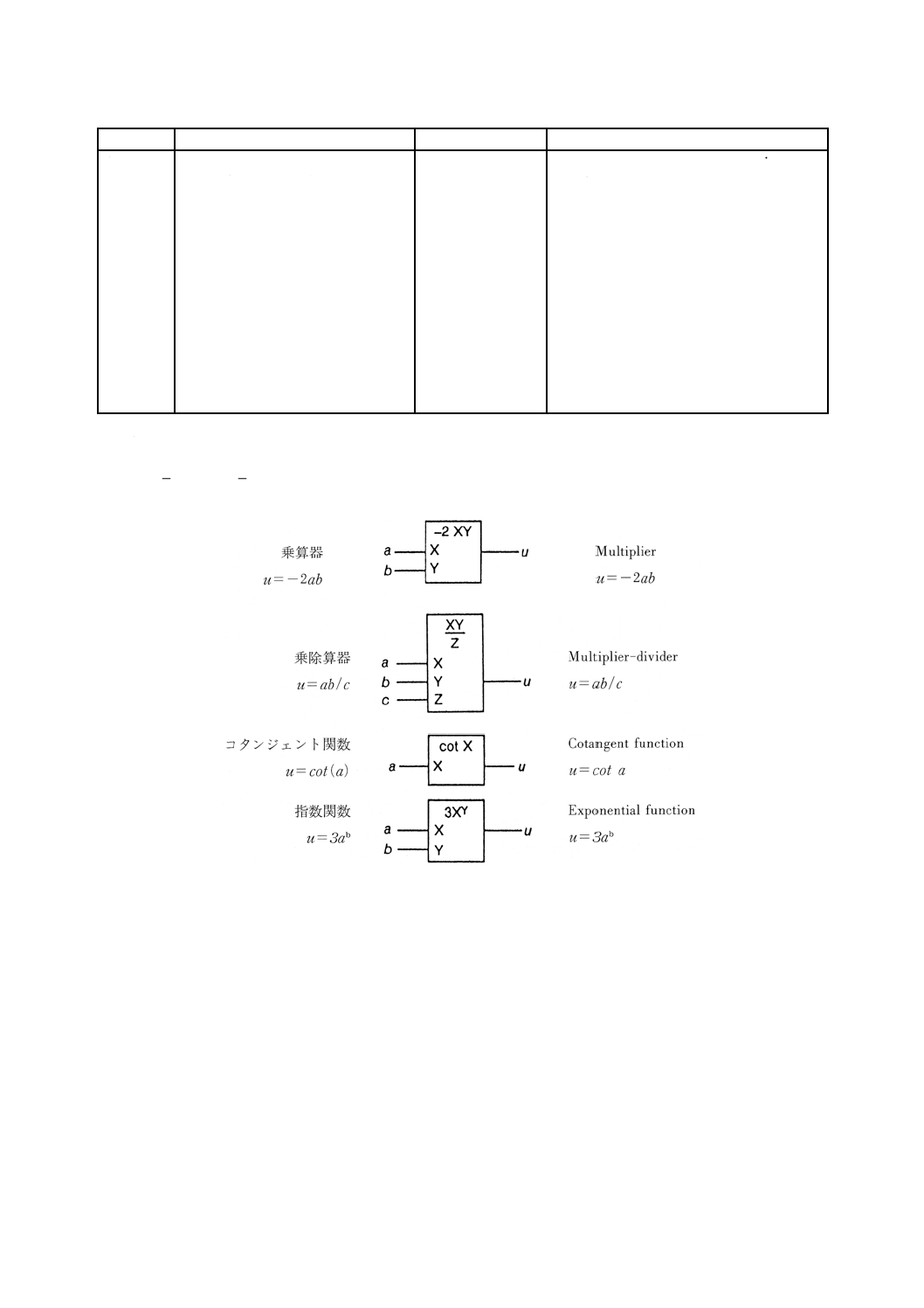
87
C 0617-13:2011
2019年7月1日の法改正により名称が変わりました。まえがきを除き,本規格中の「日本工業規格」を「日本産業規格」に読み替えてください。
注釈番号
注釈
被適用図記号
IEC 60617情報(参考)
A00353
入力及び出力は事実上デジタルであ
る。注釈A00321も参照。
13-05-16,13-05-17,
13-05-18,13-05-19,
13-05-20,13-05-21,
13-05-22,13-05-23,
13-05-24,13-05-25
S01748,S01749,
S01750,S01751,
S01752,S01768,
S01769,S01770,
S01771,S01772,
S01773,S01774,
S01775,S01776,
S01777
The inputs and outputs are digital in nature.
See also A00321.
注釈の説明図を次に表示する。
A00323̲Illustration̲EN
説明図 Illustration
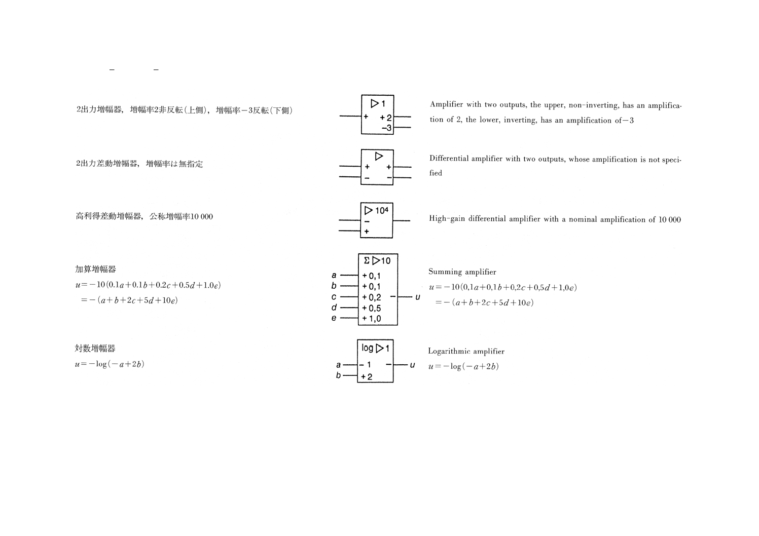
88
C 0617-13:2011
2019年7月1日の法改正により名称が変わりました。まえがきを除き,本規格中の「日本工業規格」を「日本産業規格」に読み替えてください。
A00325̲Illustration̲EN
説明図 Illustration
2
C
0
6
1
7
-1
3
:
2
0
11
2019年7月1日の法改正により名称が変わりました。まえがきを除き、本規格中の「日本工業規格」を「日本産業規格」に読み替えてください。
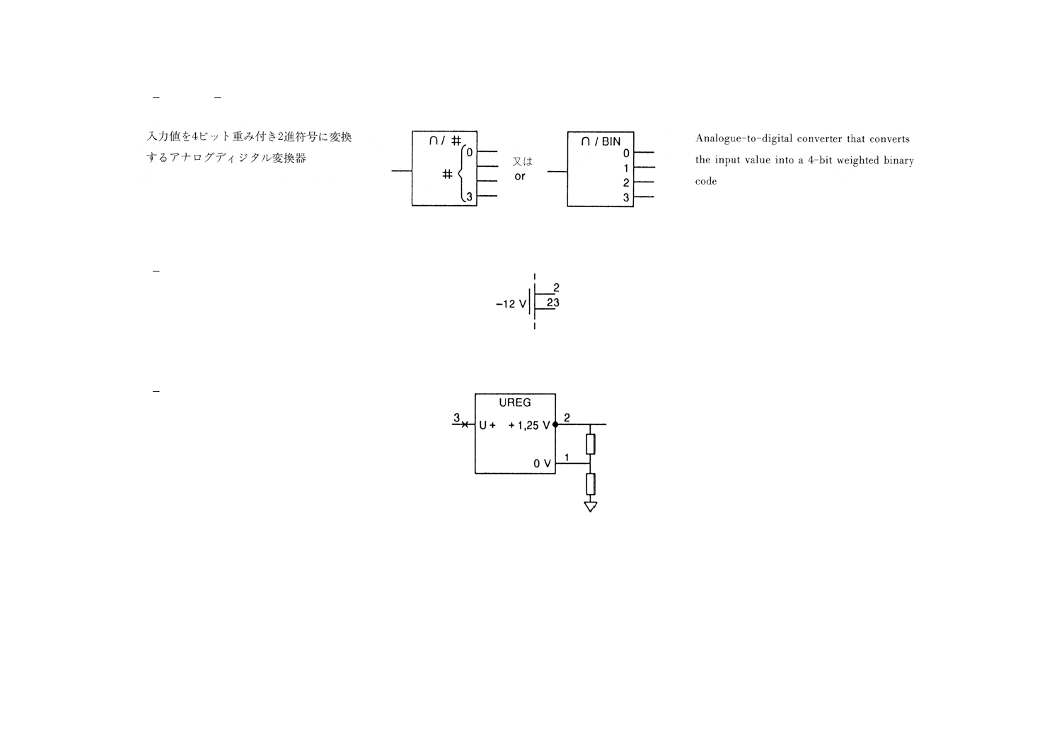
89
C 0617-13:2011
2019年7月1日の法改正により名称が変わりました。まえがきを除き,本規格中の「日本工業規格」を「日本産業規格」に読み替えてください。
A00327̲Illustration̲EN
説明図 Illustration
A00328̲Illustration
A00330̲Illustration
2
C
0
6
1
7
-1
3
:
2
0
11
2019年7月1日の法改正により名称が変わりました。まえがきを除き、本規格中の「日本工業規格」を「日本産業規格」に読み替えてください。
90
C 0617-13:2011
2019年7月1日の法改正により名称が変わりました。まえがきを除き,本規格中の「日本工業規格」を「日本産業規格」に読み替えてください。
附属書A
(参考)
参考文献
JIS C 0452-1 電気及び関連分野−工業用システム,設備及び装置,並びに工業製品−構造化原理及び参
照指定−第1部:基本原則
注記 対応国際規格:IEC 61346-1,Industrial systems, installations and equipment and industrial products
−Structuring principles and reference designations−Part 1: Basic rules(IDT)
JIS Z 8202(規格群) 量及び単位
JIS Z 8222-2 製品技術文書に用いる図記号のデザイン−第2部:参照ライブラリ用図記号を含む電子化
形式の図記号の仕様,及びその相互交換の要求事項
注記 対応国際規格:IEC 81714-2,Design of graphical symbols for use in the technical documentation of
products−Part 2: Specification for graphical symbols in a computer sensible form, including graphical
symbols for a reference library, and requirements for their interchange(IDT)
JIS Z 8222-3 製品技術文書に用いる図記号のデザイン−第3部:接続ノード,ネットワーク及びそのコ
ード化の分類
注記 対応国際規格:IEC 81714-3,Design of graphical symbols for use in the technical documentation of
products−Part 3: Classification of connect nodes, networks and their encoding(IDT)
IEC 60050 (all parts),International Electrotechnical Vocabulary
IEC 60445:2006,Basic and safety principles for man-machine interface, marking and identification−
Identification of equipment terminals and conductor terminations
IEC/TR 61352,Mnemonics and symbols for integrated circuits
IEC/TR 61734,Application of symbols for binary logic and analogue elements